Renault Clio: Front driveshaft gaiter, wheel side: Removal - Refitting
M4R, and TL4
REMOVAL
I - REMOVAL PREPARATION OPERATION
- Remove the driveshaft on the side concerned (see 29A, Driveshafts, Front right-hand driveshaft: Removal - Refitting, 29A-9) or (see 29A, Driveshafts, Front left-hand driveshaft: Removal - Refitting, 29A-2).
II - OPERATION FOR REMOVAL OF PART CONCERNED
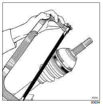
- Cut the clips taking care not to damage the groove of the stub axle bowl.
- Push back the gaiter to release the stub axle bowl.
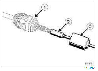
- Remove the stub axle bowl (1) using the (Tav. 1796) (2) and the extractor (Emb. 880) (3).
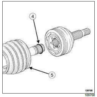
- Remove:
- the locking spring ring (4),
- the gaiter (5).
- Remove as much grease as possible from the stub axle bowl.
REFITTING
I - REFITTING OPERATION FOR PART CONCERNED
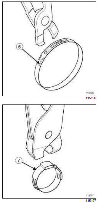
- Use:
- the (Tav. 1784) for the clip with profile end (6),
- the (Tav. 1168) for the jubilee type clip (7).
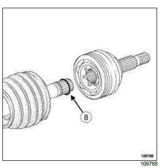
- Always replace the locking spring ring (8) each time the stub axle bowl is removed.
- Fit the small clip.
- Fit the gaiter.
- Fit the stub axle bowl manually until the locking spring ring clicks behind the ball hub.
- Spread the quantity of grease around the gaiter and the stub axle bowl.
- Insert the lips of the gaiter into the grooves of the stub axle bowl and propeller shaft.
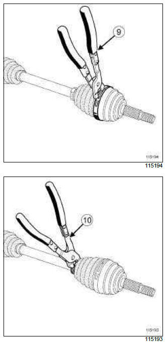
- Fit the clips, tightening them using the (Tav. 1784) (9) or the (Tav. 1168) (10) depending on the type of clip.
II - FINAL OPERATION.
- Refit the driveshaft on the side concerned (see 29A, Driveshafts, Front right-hand driveshaft: Removal - Refitting, 29A-9) or (see 29A, Driveshafts, Front left-hand driveshaft: Removal - Refitting, 29A-2).
READ NEXT:
 Front right-hand driveshaft gaiter, gearbox side: Removal - Refitting
DP0 or JH3 or JR5 or TL4
Deflector
Propeller shaft
Driveshaft yoke sleeve
Spider
RC gaiter
Tightening clip
Lock ring
Tightening ring
REMOVAL
I - REMOVAL PREPARATION OPERATION
Position the
Front left-hand driveshaft gaiter, gearbox side: Removal - Refitting
DP0 or JH3 or JR5 or TL4
Tightening clip
Tightening ring
Cup
Driveshaft yoke sleeve
Deflector
Propeller shaft
RC gaiter
Spider
Lock ring
Spring
REMOVAL
I - REMOVAL PREPARATION OPERATION
Chassis
The Renault Clio IV (2014-2019) features a well-engineered chassis that contributes to its handling, stability, and overall driving dynamics. The chassis is designed to provide a balanced and controll
SEE MORE:
Automatic gearbox
Selector lever 1
P: park
R: reverse
N: Neutral
D: automatic mode
M: manual mode
+: upper gear
–: lower gear
4: displays the gear engaged in manual
mode.
Note: Press the button 2 to go from position
D or N to R or P.
Operation
With the selection lever 1 in position P,
switch o
Brake compensator: Removal - Refitting
WITHOUT ANTI-LOCK BRAKING SYSTEM
REMOVAL
I - REMOVAL PREPARATION OPERATION
Position the vehicle on a two-post lift (see Vehicle:
Towing and lifting) (MR 392, 02A, Lifting equipment).
Fit the tool pedal press in order to limit the outflow
of the brake fluid.
WARNING
Prepare for the flow of flu
© 2016-2024 Copyright Renault Clio Owners Club
