Renault Clio: K4J or K4M or K9K or M4R, and Left-hand Drive
REMOVAL
I - REMOVAL PREPARATION OPERATION
- Position the vehicle on a two-post lift (see Vehicle: Towing and lifting) (MR 392, 02A, Lifting equipment).
- Remove:
- the battery (see Battery: Removal - Refitting) (MR 392, 80A, Battery).
- the air filter box (see Air filter unit: Removal - Refitting) (MR 392, 12A, Fuel mixture),
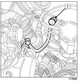
- the non-return valve (1) from the servo,
- the master cylinder (see 37A, Mechanical component controls, Master cylinder: Removal - Refitting, 37A-2),
- the lower cover strip,
- the side section of the lower cover.
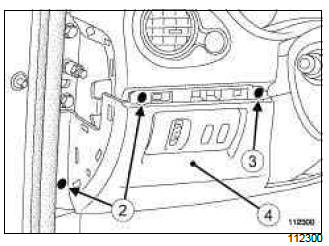
- Remove:
- the bolts (2),
- the clip (3),
- the lower cover (4), disconnecting the various connectors.
II - OPERATION FOR REMOVAL OF PART CONCERNED
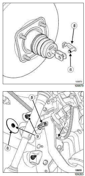
- Remove:
- the double safety connecting shaft (5) from between the brake servo pushrod and the brake pedal, and, after tilting the connecting shaft upwards, move ring (6) using a flat-blade screwdriver.
- the connector (7) from the accelerator pedal,
- the accelerator pedal connector wiring harness clip,
- the blanking cover (8) from the brake servo mounting nut,
- the brake servo mounting nuts (9),
- the brake servo.
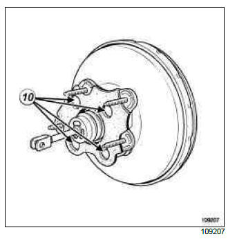
- Remove:
- the mounting bolts (10) from the brake servo spacer,
- the brake servo spacer.
REFITTING
I - REFITTING PREPARATIONS OPERATION
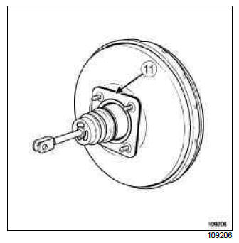
- Check that the brake servo seal (11) is present; replace the seal if it is faulty.
- The shaft connecting the brake servo pushrod and the brake pedal must be replaced every time it is removed.
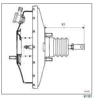
- Check the following dimension before refitting: (X1) = 171 mm.
II - REFITTING OPERATION FOR PART CONCERNED
- Refit:
- the brake servo spacer,
- the brake servo spacer mounting bolts.
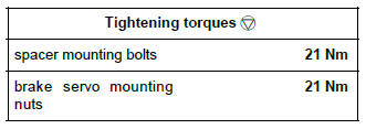
- Torque tighten the spacer mounting bolts (21 Nm).
- Refit:
- the brake servo,
- the brake servo mounting nuts.
- The shaft connecting the brake servo pushrod and the brake pedal must be refitted from right to left, and from top to bottom.
- Torque tighten the brake servo mounting nuts (21 Nm).
- Refit:
- the brake servo mounting nut blanking cover,
- the accelerator pedal connector wiring harness clip,
- the accelerator pedal connector.
III - FINAL OPERATION.
- Refit:
- the lower cover, connecting the various connectors.
- the clip,
- the bolts,
- the side section of the lower cover.
- the lower cover strip,
- the master cylinder (see 37A, Mechanical component controls, Master cylinder: Removal - Refitting, 37A-2),
- the air filter box (see Air filter unit: Removal - Refitting) (MR 392, 12A, Fuel mixture),
- the battery (see Battery: Removal - Refitting) (MR 392, 80A, Battery).
- Reconnect the non-return valve at the servo.
- Bleed the brake circuit (see 30A, General information, Braking circuit: Bleed, 30A-4).
IMPORTANT
Check that the brake servo pushrod-brake pedal connecting shaft is locked in place.
- Adjust the brake light switch (see 37A, Mechanical component controls, Brake pedal switch: Removal - Refitting, 37A-79).
READ NEXT:
 K9K, and Right-hand Drive
REMOVAL
I - REMOVAL PREPARATION OPERATION
Position the vehicle on a two-post lift (see Vehicle:
Towing and lifting) (MR 392, 02A, Lifting equipment).
Disconnect the battery (see Battery: Removal
D4F, and Left-hand Drive
REMOVAL
I - REMOVAL PREPARATION OPERATION
Put the vehicle on a two-post lift (see Vehicle: Towing and lifting).
Disconnect the battery (see Battery: Removal - Refitting).
Remove:
the non-ret
K4J or K4M, and Right-hand Drive
REMOVAL
I - REMOVAL PREPARATION OPERATION
Position the vehicle on a two-post lift (see Vehicle:
Towing and lifting) (MR 392, 02A, Lifting equipment).
Disconnect the battery (see Battery: Removal
SEE MORE:
Sequential gearbox engine speed sensor: Removal - Refitting
D4F, and JA3
REMOVAL
I - REMOVAL PREPARATION OPERATION
IMPORTANT
Before any operation on the sequential system,
discharge the accumulator using the Diagnostic
tool.
To discharge the accumulator, run command
" Discharge pressure accumulator " AC081.
To confirm the pressure drop, read the " Hydr
Start button: Removal - Refitting
VEHICLE WITH CARD
REMOVAL
I - REMOVAL PREPARATION OPERATION
Remove the centre console (see Centre console:
Removal - Refitting) (MR 393, 57A, Interior equipment).
Unclip the trim at (1) and (2).
RADIO NO. 01 or RADIO NO. 02 or RADIO NO.03
or RADIO NO. 04 or RADIO NO. 05 or RADIO NO.06
Rem
© 2016-2024 Copyright Renault Clio Owners Club
