Renault Clio: Dashboard cross member: Removal - Refitting
Note: In the event of a front impact with triggering of airbags, check the area of connection between both diameters of the beam. If there is any damage visible to the naked eye, this part must be replaced.
REMOVAL
I - REMOVAL PREPARATION OPERATION
- Remove:
- the front doors (see 47A, Side opening elements, Front side door: Removal - Refitting, 47A- 1),
- the dashboard (see Dashboard: Removal - Refitting) (MR 393, 57A, Interior equipment),
- the steering column (see Steering column: Removal - Refitting), partially (MR 392, 36A, Steering assembly).
II - OPERATION FOR REMOVAL OF PART CONCERNED
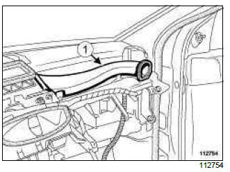
- Unclip:
- the wiring harness,
- the air ducts (1) from both sides of the vehicle.
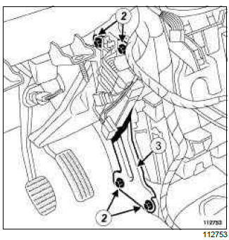
- Remove:
- the reinforcement mounting bolts (2),
- the reinforcement (3).
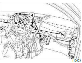
- Remove the dashboard cross member mounting bolts (4).
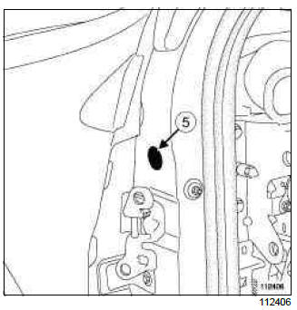
- Remove the blanking cover (5).
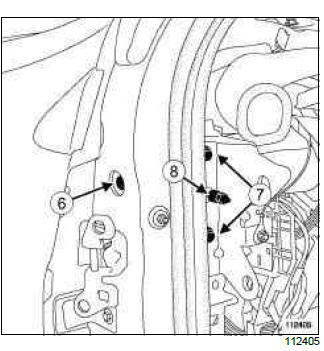
- Remove:
- the side mounting bolt (6),
- the mounting bolts (7).
- Loosen the centring device (8) in order to align the holes in the A-pillar lining with the dashboard cross member lock nuts.
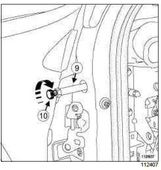
- Fit the (Car. 1765) as far as the stop (9).
- Screw the rod (10) onto the tool body (9) as far as the stop.
- Firmly lock tool body in the same way as a lock nut against the dashboard cross member nut while holding the hexagon bolt.
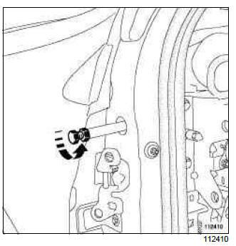
- Unscrew the whole tool as far as the stop and tighten it gently (during this operation, the beam nut, which has a left-hand thread, screws into the beam and disengages it from the A-pillar).
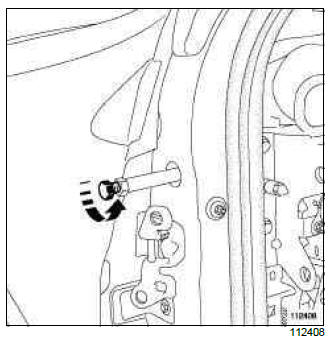
- Hold the tool body (9) and unlock the rod (10).
- Unscrew dashboard cross member rod to remove the tool.
- Remove:
- the mounting bolt (6) from the other side of the vehicle,
- the dashboard cross member.
Note: To maintain the adjustment of the dashboard cross member and therefore make refitting easier, only loosen the lock nut on one side.
REFITTING
I - REFITTING OPERATION FOR PART CONCERNED
- Fully tighten the locking nut (left-hand thread) in the beam.
- Refit:
- the dashboard cross member,
- the mounting bolts (7) to position the cross member,
- the side mounting bolt (6) on the side where the lock nut has not been adjusted.
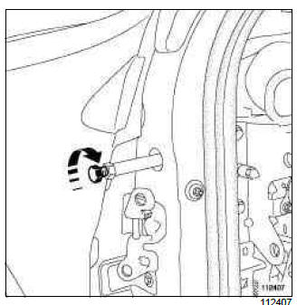
- Fit the (Car. 1765) as far as the stop.
- Screw the rod (10) onto the body (9) as far as the stop.
- Firmly lock tool body in the same way as a lock nut against the dashboard cross member nut while holding the hexagon bolt.
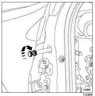
- Screw the entire tool as far as the stop and then tighten gently.
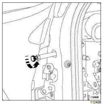
- Hold the tool body (9) and unlock the rod (10).
- Unscrew dashboard cross member rod to remove the tool.
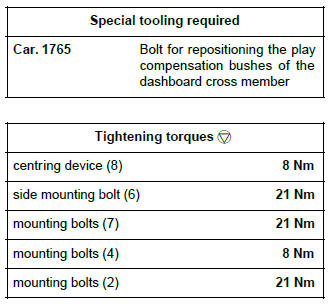
- Torque tighten the centring device (8) (8 Nm).
- Refit:
- the side mounting bolt (6),
- the mounting bolts (4).
- Torque tighten:
- the side mounting bolt (6) (21 Nm),
- the mounting bolts (7) (21 Nm),
- the mounting bolts (4) (8 Nm).
- Refit:
- the reinforcement (3),
- the mounting bolts (2).
- Torque tighten the mounting bolts (2) (21 Nm).
- Clip on:
- the air duct (1) on both sides of the vehicle,
- the wiring harness.
II - FINAL OPERATION
- Refit:
- the steering column (see Steering column: Removal - Refitting) (MR 392, 36A, Steering assembly),
- the dashboard (see Dashboard: Removal - Refitting) (MR 393, 57A, Interior equipment),
- the front doors (see 47A, Side opening elements, Front side door: Removal - Refitting, 47A- 1).
Windscreen aperture lower cross member closure panel: General description
WARNING
The information contained in the following describes the general repair procedure for all vehicles having the same design for this part.
Before reading the following general information, make sure that there are no special notes associated with the vehicle. These special notes are specified if necessary in other parts of the sub-section dealing with the component.
Note: For a detailed description of a particular connection, see MR 400, 40A, General Information.
DESIGN OF THE STRUCTURAL COMPONENT
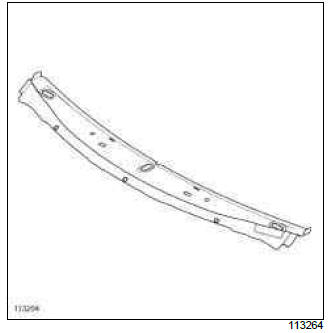
This is a basic part; it only fulfils the function of the windscreen aperture lower cross member closure panel.
Windscreen aperture lower cross member closure panel: Description
There is only one way of replacing this part:
- partial replacement.
I - COMPOSITION OF THE SPARE PART
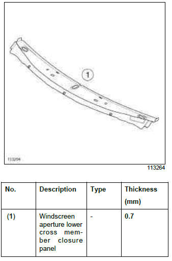
II - PART IN POSITION
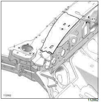
(X1) = 50 mm
Preserve the windscreen aperture lower cross member when the cut is made.
WARNING
If the spot welds cannot be made as they were originally using an electric spot welding machine, they should be replaced with plug welds after holes have been drilled in the first panel.
III - POSITIONING OF LOCAL ELECTRICAL EARTHS
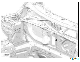
IMPORTANT
To avoid damaging the vehicles electric and electronic components, the earths of any wiring harness near the weld area must be disconnected.
The welding machine earth must be placed as close as possible to the weld zone.
Bulkhead lower cross member: General description
WARNING
Before reading the following general information, make sure that there are no special notes associated with the vehicle. These special notes are specified if necessary in other parts of the sub-section dealing with the component.
Note: For a detailed description of a particular connection, see MR 400, 40A, General Information.
DESIGN OF THE STRUCTURAL COMPONENT
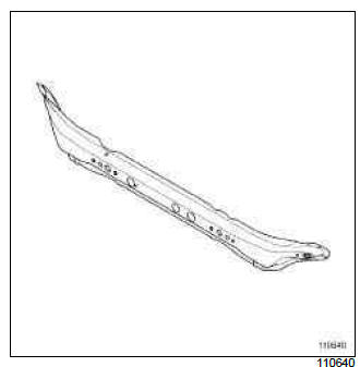
This is a basic part; it simply fulfils the function of a bulkhead cross member.
WARNING
If the spot welds cannot be made as they were originally using an electrical spot welding machine, they should be replaced with plug welds after holes have been drilled in the first panel.
Bulkhead side reinforcement: General description
WARNING
The information contained in the following describes the general repair procedure for all vehicles having the same design for this part.
Before reading the following general information, make sure that there are no special notes associated with the vehicle. These special notes are specified if necessary in other parts of the sub-section dealing with the component.
Note: For a detailed description of a particular connection, see MR 400, 40A, General Information.
DESIGN OF THE STRUCTURAL COMPONENT
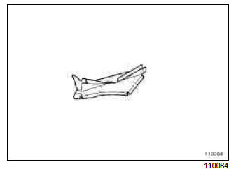
This is a basic part, it simply fulfils the function of bulkhead side reinforcement.
If there are other issues regarding access to mating faces, the various replacement options are described in the basic instructions for structural bodywork repair (see MR 400, 40A, General Information).

