Renault Clio: Rear wiring: Removal - Refitting
B85 or K85
IMPORTANT
Consult the safety and cleanliness advice and operation recommendations before carrying out any repair (see 88A, Wiring harness, Wiring: Precautions for the repair, 88A-5).
IMPORTANT
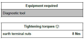
To avoid any risk of triggering when working on or near a pyrotechnic component (airbags or pretensioners), lock the airbag computer using the diagnostic tool.
When this function is activated, all the trigger lines are inhibited and the airbag warning light on the instrument panel lights up continuously (ignition on).
IMPORTANT
Never handle the pyrotechnic systems (pretensioners or airbags) near to a source of heat or naked flame - they may be triggered.
WARNING
To prevent damage to the wiring harness when refitting, observe the original routing.
REMOVAL
I - REMOVAL PREPARATION OPERATION
- Position the vehicle on a two-post lift (see Vehicle: Towing and lifting) (MR 392, 02A, Lifting equipment).
- Lock the airbag computer using the Diagnostic tool (see MR 394 Electricity, 88C, Airbags and pretensioners).
- Switch off the ignition.
- Disconnect the battery (see 80A, Battery, Battery: Removal - Refitting, 80A-1).
WARNING
To prevent damaging the connectors, consult the disconnection procedure (see Connector: Disconnection and reconnection) (Technical Note 6015A, 88A, Wiring).
- Remove:
- the front seats (see Complete front seat: Removal - Refitting) (MR 393, 75A, Front seat frames and runners),
- the rear bench seat base (see Single unit rear bench seat base: Removal - Refitting) or (see 1/ 3 and 2/3 rear bench seat base: Removal - Refitting) (depending on the equipment level) (MR 393, 76A, Rear seat frames and runners),
- the rear bench seatback (see Single unit rear bench seatback: Removal - Refitting) or (see 1/3 and 2/3 rear bench seatback: Removal - Refitting) (depending on the equipment level) (MR 393, 76A, Rear seat frames and runners),
- the quarter panel trims (see Quarter panel trim: Removal - Refitting) (MR 393, 71A, Body internal trim),
- the wheel arch trims (see Rear wheel arch trim: Removal - Refitting) (MR 393, 71A, Body internal trim),
- the front door sill inner trims (see Front door sill lining: Removal - Refitting) (MR 393, 71A, Body internal trim),
- the rear door sill trims (see Rear door sill lining: Removal - Refitting) (MR 393, 71A, Body internal trim),
- the centre console (see Centre console: Removal - Refitting) (MR 393, 57A, Interior equipment),
- the rear centre floor carpet (see Centre floor rear carpet: Removal - Refitting) (MR 393, 71A, Body internal trim),
- the front centre floor carpet (see Centre floor front carpet: Removal - Refitting) (MR 393, 71A, Body internal trim),
- the centre floor lateral soundproofing (see Centre floor side soundproofing: Removal - Refitting) (MR 393, 68A, Soundproofing),
- the centre floor rear soundproofing (see Centre floor rear soundproofing: Removal - Refitting) (MR 393, 68A, Soundproofing),
- the tailgate trim (see Tailgate trim: Removal - Refitting) (MR 393, 73A, Non-side opening elements trim),
- the rear lights on the wing (see 81A, Rear lighting, Rear wing light: Removal - Refitting, 81A- 5).
II - OPERATION FOR REMOVAL OF PART CONCERNED
WARNING
To prevent any risk of noise, premature wear, short circuits, etc. after the refitting operation, mark the wiring routing and how to connect the connectors.
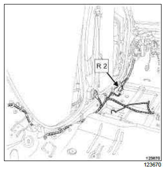
- Disconnect the R 2 connector.
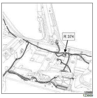
- Disconnect the R 374 connector.
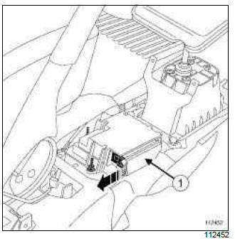
- Unclip the lock from the airbag computer connector.
- Disconnect the (1) airbag computer connector.
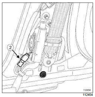
- Disconnect the connector (2) from the front right-hand and left-hand pyrotechnic inertia reel.
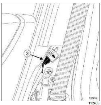
- Disconnect the connector (3) from the right-hand and left-hand impact sensor.
LEFT-HAND DRIVE
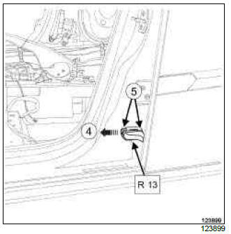
- Unclip the lock (4) from the R 13 connector.
- Disconnect the R 13 connector.
- Remove the bolts (5) of the R 13 connector.
- Extract the wiring of the B-pillar.
RIGHT-HAND DRIVE
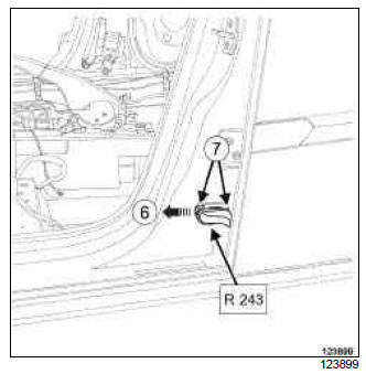
- Unclip the lock (6) from the R 243 connector.
- Disconnect the R 243 connector.
- Remove the bolts (7) of the R 243 connector.
- Extract the wiring of the B-pillar.
LEFT-HAND DRIVE
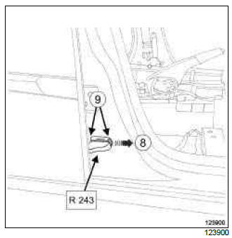
- Unclip the lock (8) from the R 243 connector.
- Disconnect the R 243 connector.
- Remove the bolts (9) of the R 243 connector.
- Extract the wiring of the B-pillar.
RIGHT-HAND DRIVE
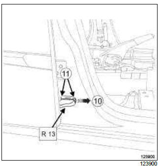
- Unclip the lock (10) from the R 13 connector.
- Disconnect the R 13 connector.
- Remove the bolts (11) of the R 13 connector.
- Extract the wiring of the B-pillar.
TYRE PRESSURE SENSOR
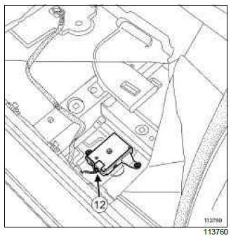
- Disconnect the connector (12) from the tyre pressure monitoring system computer.
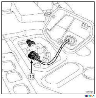
- Open the fuel gauge flap.
- Disconnect the connector (13) from the fuel gauge.
VEHICLE WITH CARD
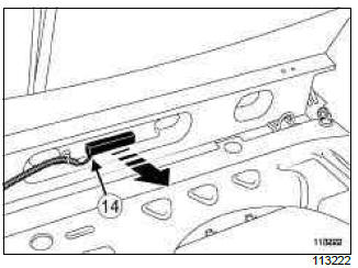
- Disconnect the (14) rear starter aerial connector.
ELECTRONIC STABILITY PROGRAM
- Remove the front right and left-hand wheel arch liners (see Rear wheel arch liner: Removal - Refitting) (MR 393, 55A, Exterior protection),
- Unclip the rear right-hand and left-hand wheel speed sensor clip.
- Disconnect the connector of the rear right-hand and left-hand wheel speed sensor.
- Extract the wiring under body.
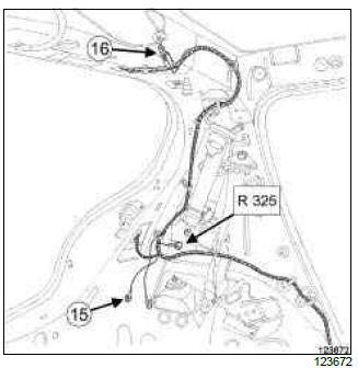
- Remove the nut (15) from the earth terminal.
- Disconnect:
- the earth terminal,
- the radio aerial (16) connector.
- the R 325 connector.
PROXIMITY RADAR
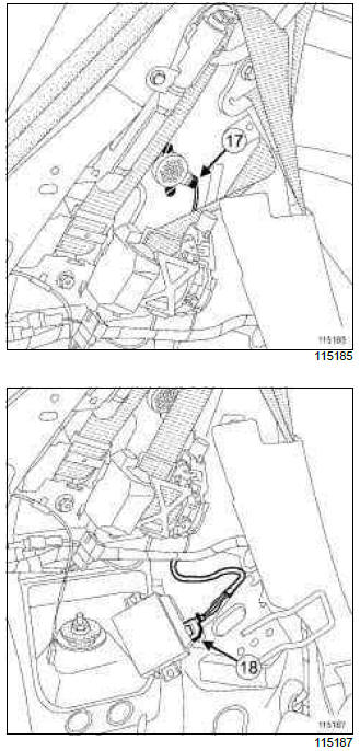
- Disconnect the connector (17) from the parking distance control buzzer.
- Remove the parking distance control computer to disconnect its connector (18) (see 87F, Parking distance control, Parking distance control computer: Removal - Refitting, 87F-6).
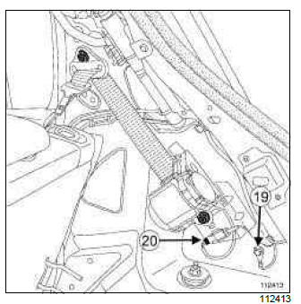
- Remove the nut (19) from the earth terminal.
- Disconnect:
- the connector (20) of the right-hand and left-hand pyrotechnic inertia reel,
- the earth terminal.
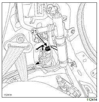
- Disconnect the connector (21) from the fuel filler flap lock motor.
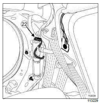
- Disconnect the connector (22) of the right-hand and left-hand side curtain airbag.
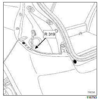
- Disconnect the connector (22) of the right-hand and left-hand side curtain airbag.
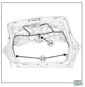
- Disconnect:
- the connectors (23) of the rear screen defrosting system,
- the connector (24) of the rear screen wiper motor.
VEHICLE WITH CARD
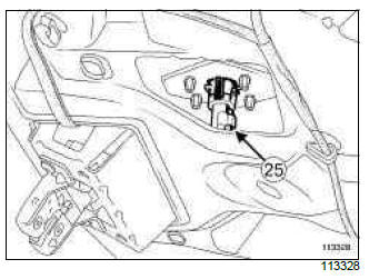
- Disconnect the connector (25) from the tailgate locking switch.
- Remove the following to disconnect the connectors:
- the tailgate lock (see Tailgate lock: Removal - Refitting),
- the tailgate opening switch (see 87C, Opening element management, Tailgate opening switch: Removal - Refitting, 87C-5),
- the high level brake light (see 81A, Rear lighting, 3rd brake light: Removal - Refitting, 81A- 10).
VEHICLE WITH CARD
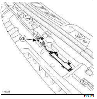
- Remove the rear bumper (see Rear bumper: Removal - Refitting) (MR 393, 55A, Exterior protection).
- Unclip the connector of the rear bumper absorber.
- Disconnect the connector (26) from the opening aerial.
- Unclip the rear wiring.
- Remove the rear wiring.
WARNING
To prevent any damage during the removal operation, check that the wiring is free from its mountings (retaining clip, plastic clip, adhesive tape, connector, etc.).
REFITTING
- If replacing with more wiring, lock the unused connectors (see Connector: Sealing and immobilisation) (Technical Note 6015A, 88A, Wiring).
I - REFITTING OPERATION FOR PART CONCERNED
- Refit the rear wiring.
- Clip on the rear wiring.
VEHICLE WITH CARD
- Connect the opening aerial connector.
- Clip the opening aerial connector onto the rear bumper absorber.
- Refit the rear bumper (see Rear bumper: Removal - Refitting) (MR 393, 55A, Exterior protection).
- Refit:
- the tailgate lock (see Tailgate lock: Removal - Refitting),
- the tailgate opening switch (see 87C, Opening element management, Tailgate opening switch: Removal - Refitting, 87C-5),
- the high level brake light (see 81A, Rear lighting, 3rd brake light: Removal - Refitting, 81A- 10).
VEHICLE WITH CARD
- Connect the tailgate locking switch connector.
- Connect:
- the rear screen defrosting connectors,
- the rear screen wiper motor connector.
- Connect:
- the R 319 connector,
- the connector of the right-hand and left-hand side curtain airbag,
- the fuel filler flap lock motor connector,
- the right-hand and left-hand earth terminals,
- the connector of the rear pyrotechnic inertia reels,
- the R 325 connector,
- the radio aerial connector.
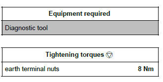
- Torque tighten the earth terminal nuts (8 Nm).
PROXIMITY RADAR
- Connect the parking distance control buzzer connector.
- Refit the parking distance control computer (see 87F, Parking distance control, Parking distance control computer: Removal - Refitting, 87F- 6).
ELECTRONIC STABILITY PROGRAM
- Fit the wiring under body.
- Connect the rear right-hand and left-hand wheel speed sensor connector.
- Clip on the right-hand and left-hand wheel speed sensor.
- Refit the front right-hand and left-hand wheel arch liners (see Rear wheel arch liner: Removal - Refitting) (MR 393, 55A, Exterior protection),
VEHICLE WITH CARD
- Connect the rear starter aerial connector.
- Connect the fuel sender connector.
- Close the fuel gauge flap.
TYRE PRESSURE SENSOR
- Connect the tyre pressure monitoring system computer connector.
- Fit the wiring onto the B-pillars.
- Refit the side door connector bolts.
- Connect the rear side door connectors.
- Clip on the rear side door connector locks.
- Connect:
- the front pyrotechnic inertia reel connectors,
- the impact sensor connectors,
- the airbag computer connector.
- Clip on the airbag computer connector lock.
- Connect:
- the R 374 connector,
- the R 2 connector.
II - FINAL OPERATION.
- Refit:
- the rear lights on the wing (see 81A, Rear lighting, Rear wing light: Removal - Refitting, 81A- 5).
- the tailgate trim (see Tailgate trim: Removal - Refitting) (MR 393, 73A, Non-side opening elements trim),
- the centre floor rear soundproofing (see Centre floor rear soundproofing: Removal - Refitting) (MR 393, 68A, Soundproofing),
- the centre floor lateral soundproofing (see Centre floor side soundproofing: Removal - Refitting) (MR 393, 68A, Soundproofing),
- the front centre floor carpet (see Centre floor front carpet: Removal - Refitting) (MR 393, 71A, Body internal trim),
- the rear centre floor carpet (see Centre floor rear carpet: Removal - Refitting) (MR 393, 71A, Body internal trim),
- the centre console (see Centre console: Removal - Refitting) (MR 393, 57A, Interior equipment),
- the rear door sill trims (see Rear door sill lining: Removal - Refitting) (MR 393, 71A, Body internal trim),
- the front door sill inner trims (see Front door sill lining: Removal - Refitting) (MR 393, 71A, Body internal trim),
- the wheel arch trims (see Rear wheel arch trim: Removal - Refitting) (MR 393, 71A, Body internal trim),
- the quarter panel trims (see Quarter panel trim: Removal - Refitting) (MR 393, 71A, Body internal trim),
- the rear bench seatback (see Single unit rear bench seatback: Removal - Refitting) or (see 1/3 and 2/3 rear bench seatback: Removal - Refitting) (depending on the equipment level) (MR 393, 76A, Rear seat frames and runners),
- the rear bench seat base (see Single unit rear bench seat base: Removal - Refitting) or (see 1/ 3 and 2/3 rear bench seat base: Removal - Refitting) (depending on the equipment level) (MR 393, 76A, Rear seat frames and runners),
- the front seats (see Complete front seat: Removal - Refitting) (MR 393, 75A, Front seat frames and runners),
- Connect the battery (see 80A, Battery, Battery: Removal - Refitting, 80A-1).
IMPORTANT
To avoid a fault with or even triggering of pyrotechnic components (airbags or pretensioners), check the airbag computer using the diagnostic tool.
- Unlock the airbag computer using the Diagnostic tool (see MR 394, 88C, Airbags and pretensioners).
C85 or S85
IMPORTANT
Consult the safety and cleanliness advice and operation recommendations before carrying out any repair (see 88A, Wiring harness, Wiring: Precautions for the repair, 88A-5).
IMPORTANT
To avoid any risk of triggering when working on or near a pyrotechnic component (airbags or pretensioners), lock the airbag computer using the diagnostic tool.
When this function is activated, all the trigger lines are inhibited and the airbag warning light on the instrument panel lights up continuously (ignition on).
IMPORTANT
Never handle the pyrotechnic systems (pretensioners or airbags) near to a source of heat or naked flame - they may be triggered.
WARNING
To prevent damage to the wiring harness when refitting, observe the original routing.
REMOVAL
I - REMOVAL PREPARATION OPERATION
- Position the vehicle on a two-post lift (see Vehicle: Towing and lifting) (MR 392, 02A, Lifting equipment).
- Lock the airbag computer using the Diagnostic tool (see MR 394, 88C, Airbags and pretensioners).
- Switch off the ignition.
- Disconnect the battery (see 80A, Battery, Battery: Removal - Refitting, 80A-1).
WARNING
To prevent damaging the connectors, consult the disconnection procedure (see Connector: Disconnection and reconnection) (Technical Note 6015A, 88A, Wiring).
- Remove:
- the front seats (see Complete front seat: Removal - Refitting) (MR 393, 75A, Front seat frames and runners),
- the rear bench seat base (see Single unit rear bench seat base: Removal - Refitting) or (see 1/ 3 and 2/3 rear bench seat base: Removal - Refitting) (depending on the equipment level) (MR 393, 76A, Rear seat frames and runners),
- the rear bench seatback (see Single unit rear bench seatback: Removal - Refitting) or (see 1/3 and 2/3 rear bench seatback: Removal - Refitting) (depending on the equipment level) (MR 393, 76A, Rear seat frames and runners),
- the rear right-hand and left-hand panel trim (see Rear panel lining: Removal - Refitting) (MR 393, 71A, Body internal trim),
- the rear quarter panel trims (see Quarter panel trim: Removal - Refitting) (MR 393, 71A, Body internal trim),
- the wheel arch trims (see Rear wheel arch trim: Removal - Refitting) (MR 393, 71A, Body internal trim),
- the front door sill inner trims (see Front door sill lining: Removal - Refitting) (MR 393, 71A, Body internal trim),
- the centre console (see Centre console: Removal - Refitting) (MR 393, 57A, Interior equipment),
- the rear centre floor carpet (see Centre floor rear carpet: Removal - Refitting) (MR 393, 71A, Body internal trim),
- the front centre floor carpet (see Centre floor front carpet: Removal - Refitting) (MR 393, 71A, Body internal trim),
- the side soundproofing of centre floor (see Centre floor side soundproofing: Removal - Refitting) (MR 393, 68A, Soundproofing),
- the rear soundproofing of centre floor (see Centre floor rear soundproofing: Removal - Refitting) (MR 393, 68A, Soundproofing),
- the tailgate trim (see Tailgate trim: Removal - Refitting) (MR 393, 73A, Non-side opening elements trim),
- the rear lights on the wing (see 81A, Rear lighting, Rear wing light: Removal - Refitting, 81A- 5).
II - OPERATION FOR REMOVAL OF PART CONCERNED
WARNING
To prevent any risk of noise, premature wear, short circuits, etc. after the refitting operation, mark the wiring routing and how to connect the connectors.
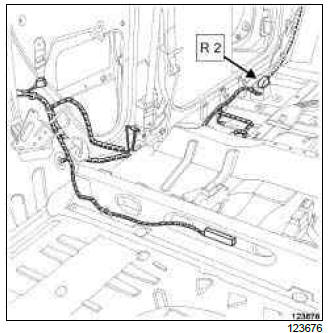
- Disconnect the R 2 connector.
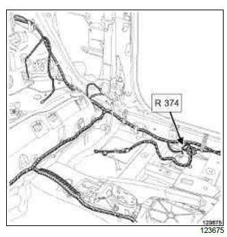
- Disconnect the R 374 connector.
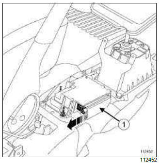
- Unclip the airbag computer connector lock.
- Disconnect the airbag computer connector (1).
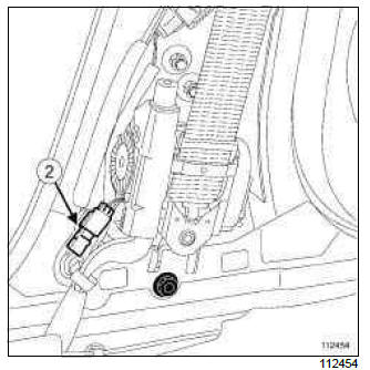
- Disconnect the front right-hand and left-hand pyrotechnic inertia reel connector (2).
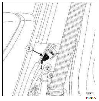
- Disconnect the right-hand and left-hand impact sensor connector (3).
TYRE PRESSURE SENSOR
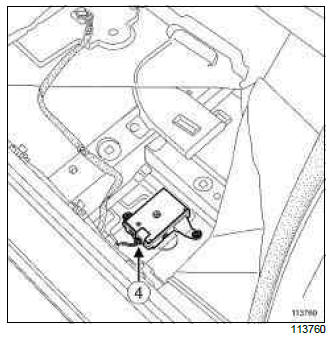
- Disconnect the tyre pressure monitoring system computer connector (4).
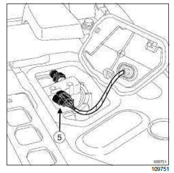
- Open the fuel gauge flap.
- Disconnect the fuel gauge connector (5).
VEHICLE WITH CARD
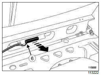
- Disconnect the rear starter aerial connector (6).
ELECTRONIC STABILITY PROGRAM
- Remove the rear right-hand and left-hand wheel arch liners (see Rear wheel arch liner: Removal - Refitting) (MR 393, 55A, Exterior protection),
- Unclip the rear right-hand and left hand wheel speed sensor clip.
- Disconnect the rear right-hand and left-hand wheel speed sensor connector.
- Extract the wiring under the body.
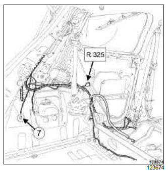
- Remove the nut (7) from the earth terminal.
- Disconnect:
- the earth terminal,
- the R 325 connector.
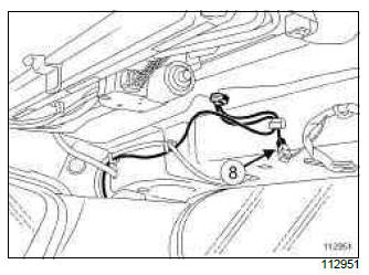
- Disconnect the radio aerial connector (8).
PROXIMITY RADAR
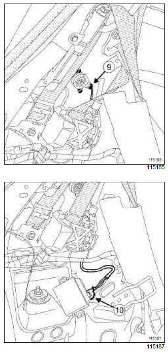
- Disconnect the connector (9) from the parking distance control buzzer.
- Remove the parking distance control computer to disconnect the connector (10) (see 87F, Parking distance control, Parking distance control computer: Removal - Refitting, 87F-6).
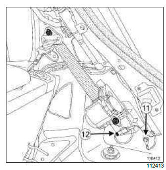
- Remove the nut (11) from the earth terminal.
- Disconnect:
- the right-hand and left-hand pyrotechnic inertia reel connector (12),
- the earth terminal.
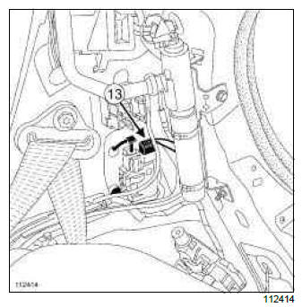
- Disconnect the connector (13) from the fuel filler flap lock motor.
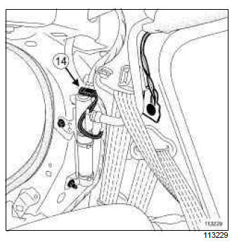
- Disconnect the left-hand and right-hand side curtain airbag connector (14).
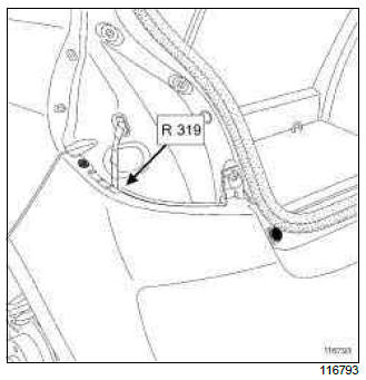
- Disconnect the R 319 connector.
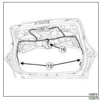
- Disconnect:
- the connectors (15) of the heated rear screen,
- the rear screen wiper motor connector (16).
VEHICLE WITH CARD
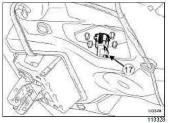
- Disconnect the connector (17) from the tailgate locking switch.
- To disconnect the connectors, remove:
- the tailgate lock (see Tailgate lock: Removal - Refitting),
- the tailgate opening switch (see 87C, Opening element management, Tailgate opening switch: Removal - Refitting, 87C-5),
- the high level brake light (see 81A, Rear lighting, 3rd brake light: Removal - Refitting, 81A- 10).
VEHICLE WITH CARD
- Remove the rear bumper (see Rear bumper: Removal - Refitting) (MR 393, 55A, Exterior protection).
- Unclip the rear bumper absorber connector.
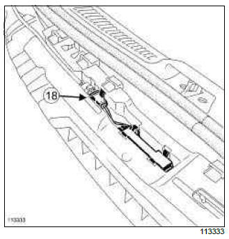
- Disconnect the connector (18) from the opening aerial.
- Unclip the rear wiring.
- Remove the rear wiring.
WARNING
To prevent any damage during the removal operation, check that the wiring is free from its mountings (retaining clip, plastic clip, adhesive tape, connector, etc.).
REFITTING
- If replacing with more wiring, lock the unused connectors (see Connector: Sealing and immobilisation) (Technical Note 6015A, 88A, Wiring).
I - REFITTING OPERATION FOR PART CONCERNED
- Refit the rear wiring.
- Clip on the rear wiring.
VEHICLE WITH CARD
- Connect the opening aerial connector.
- Clip the opening aerial connector onto the rear bumper absorber.
- Refit the rear bumper (see Rear bumper: Removal - Refitting) (MR 393, 55A, Exterior protection).
- Refit:
- the tailgate lock (see Tailgate lock: Removal - Refitting),
- the tailgate opening switch (see 87C, Opening element management, Tailgate opening switch: Removal - Refitting, 87C-5),
- the high level brake light (see 81A, Rear lighting, 3rd brake light: Removal - Refitting, 81A- 10).
VEHICLE WITH CARD
- Connect the tailgate locking switch connector.
- Connect:
- the heated rear screen connectors,
- the rear screen wiper motor connector.
- Connect:
- the R 319 connector,
- the right-hand and left-hand side curtain airbag connector,
- the fuel filler flap locking motor connector,
- the right-hand and left-hand earth terminals,
- the rear pyrotechnic inertia reel connector,
- the R 325 connector,
- the radio aerial connector.
- Torque tighten the earth terminal nuts (8 Nm).
PROXIMITY RADAR
- Connect the parking distance control buzzer connector.
- Refit the parking distance control computer (see 87F, Parking distance control, Parking distance control computer: Removal - Refitting, 87F- 6).
ELECTRONIC STABILITY PROGRAM
- Fit the wiring under the body.
- Connect the rear right-hand and left-hand wheel speed sensor connector.
- Clip on the right-hand and left-hand wheel speed sensor clip.
- Refit the rear right-hand and left-hand wheel arch liners (see Rear wheel arch liner: Removal - Refitting) (MR 393, 55A, Exterior protection).
VEHICLE WITH CARD
- Connect the rear starter aerial connector.
- Connect the fuel sender connector.
- Close the fuel gauge flap.
TYRE PRESSURE SENSOR
- Connect the tyre pressure monitoring computer connector.
- Connect:
- the connector for the front pyrotechnic inertia reels,
- the connector for the impact sensors,
- the airbag computer connector.
- Clip on the airbag computer connector lock.
- Connect:
- the R 374 connector,
- the R 2 connector.
II - FINAL OPERATION.
- Refit:
- the rear lights on the wing (see 81A, Rear lighting, Rear wing light: Removal - Refitting, 81A- 5).
- the tailgate trim (see Tailgate trim: Removal - Refitting) (MR 393, 73A, Non-side opening elements trim),
- the rear soundproofing of centre floor (see Centre floor rear soundproofing: Removal - Refitting) (MR 393, 68A, Soundproofing),
- the side soundproofing of centre floor (see Centre floor side soundproofing: Removal - Refitting) (MR 393, 68A, Soundproofing),
- the front centre floor carpet (see Centre floor front carpet: Removal - Refitting) (MR 393, 71A, Body internal trim),
- the rear centre floor carpet (see Centre floor rear carpet: Removal - Refitting) (MR 393, 71A, Body internal trim),
- the centre console (see Centre console: Removal - Refitting) (MR 393, 57A, Interior equipment),
- the rear panel trims (see Rear panel lining: Removal - Refitting) (MR 393, 71A, Body internal trim),
- the front door sill inner trims (see Front door sill lining: Removal - Refitting) (MR 393, 71A, Body internal trim),
- the wheel arch trims (see Rear wheel arch trim: Removal - Refitting) (MR 393, 71A, Body internal trim),
- the rear quarter panel trims (see Quarter panel trim: Removal - Refitting) (MR 393, 71A, Body internal trim),
- the rear bench seatback (see Single unit rear bench seatback: Removal - Refitting) or (see 1/3 and 2/3 rear bench seatback: Removal - Refitting) (depending on the equipment level) (MR 393, 76A, Rear seat frames and runners),
- the rear bench seat base (see Single unit rear bench seat base: Removal - Refitting) or (see 1/ 3 and 2/3 rear bench seat base: Removal - Refitting) (depending on the equipment level) (MR 393, 76A, Rear seat frames and runners),
- the front seats (see Complete front seat: Removal - Refitting) (MR 393, 75A, Front seat frames and runners),
- Connect the battery (see 80A, Battery, Battery: Removal - Refitting, 80A-1).
IMPORTANT
To avoid a fault with or even triggering of pyrotechnic components (airbags or pretensioners), check the airbag computer using the diagnostic tool.
- Unlock the airbag computer using the Diagnostic tool (see MR 394, 88C, Airbags and pretensioners).

