Renault Clio: Front axle subframe: Removal - Refitting
EQUIPMENT LEVEL E3 LEISURE or EQUIPMENT LEVEL EA1 or EQUIPMENT LEVEL EA2 or EQUIPMENT LEVEL EA3 or EQUIPMENT LEVEL EA4 or EQUIPMENT LEVEL EA5 or EQUIPMENT LEVEL EAG
WARNING
Do not use the lower arm for support with a lifting system.
REMOVAL
I - REMOVAL PREPARATION OPERATION
- Position the vehicle on a two-post lift (see Vehicle: Towing and lifting) (02A, Lifting equipment).
- Remove the front wheels (see 35A, Wheels and tyres, Wheel: Removal - Refitting, 35A-1).
- Strap the cooling radiator by the cooling radiator top hose and the bonnet opening striker plate.
II - OPERATION FOR REMOVAL OF PART CONCERNED
- Lift the floor carpet to access the universal joint bolt.
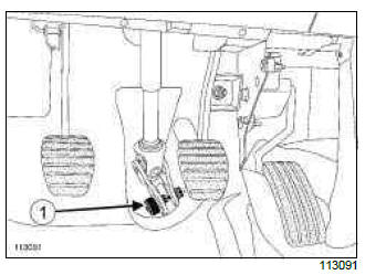
- Remove the universal joint cover (1) (do not keep).
- Set the wheels straight ahead.
- Position the flywheel immobiliser.
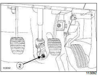
- Remove the universal joint bolt (2) (do not keep),
WARNING
Tilt the universal joint to detach it from the pinion; do not pull out the intermediate shaft.
- Remove the universal joint from the steering rack.
- Remove:
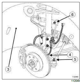
- the wheel arch (see Front wheel arch liner: Removal - Refitting) protectors (3) (55A, Exterior protection),
- the engine undertray.
- Unclip the wheel speed sensors (4) in the hub carrier.
- Remove:
- the track rod end nuts (5),
- the anti-roll bar tie-rod upper ball joint nuts (6).
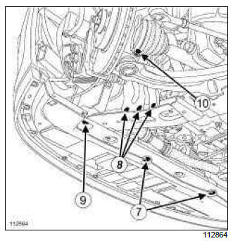
- Remove:
- the lower bumper bolts (7),
- the side stiffener lower bolts (8),
- the radiator cross member bolts (9),
- the radiator cross member,
- the lower ball joint stud (10).
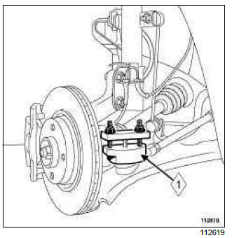
-
Remove:
-
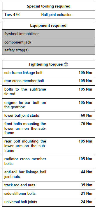
the track rod end using the (Tav. 476) (1),
-
the anti-roll bar tie-rod upper ball joints.
-
JH3 or JR5
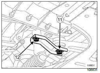
- Remove the bolt (11) from the engine tie-bar on the gearbox.
- Loosen the bolt (12) on the engine tie-bar retaining bracket in order to be able to turn the retaining bracket.
DP0
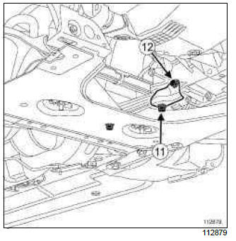
- Remove the mounting bolt (11) from the engine tie-bar on the gearbox.
- Loosen the bolt (12) on the engine tie-bar retaining bracket in order to be able to turn the tie-bar.
TL4
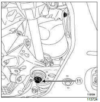
- Remove the engine tie-bar bolt (11).
- Fit the component jack underneath the subframe.
- Strap the subframe to the component jack.
- Remove the lower arm ball joints.
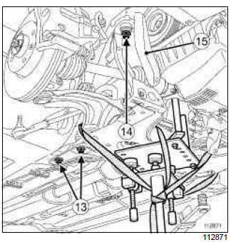
- Remove:
- the rear cross member bolts (13),
- the rear cross member,
- the subframe bolts (14) on the body,
- the side reinforcements (15).
- Lower the subframe by approximately 5 cm using the component jack.
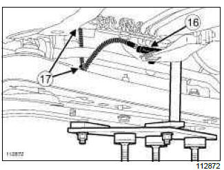
- Disconnect the oxygen sensor connector (16).
- Unclip the wiring (17) from the oxygen sensor.
- Disconnect (if fitted to the vehicle):
- the connector on the xenon bulb position sensor,
- the xenon bulb position sensor wiring harness connector under the wheel arch.
- Unclip the xenon bulb position sensor wiring (if fitted to the vehicle).
- Remove the sub-frame.
Subframe without xenon bulb
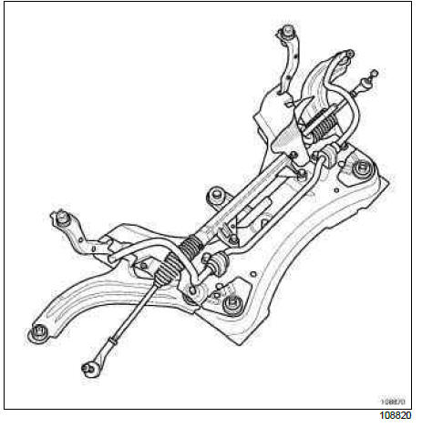
Subframe with xenon bulb
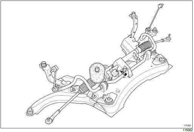
- Remove the subframe fittings.
REFITTING
I - REFITTING PREPARATION OPERATION
- Always replace the following after each removal
operation:
- the anti-roll bar link rod brake nuts,
- the universal joint bolt and cam nut.
- Degrease the contact surface areas of the subframe and the body using SURFACE CLEANER (see Vehicle: Parts and consumables for the repair) (04B, Consumables - Products).
II - REFITTING OPERATION FOR PART CONCERNED
- Refit the subframe equipment.
- Degrease the surfaces of the body which are in contact with the sub-frame and the cross member using surface cleaner.
- Position the subframe using component jack.
- Clip on the xenon bulb position sensor wiring harness (if fitted to the vehicle).
- Connect (if fitted to the vehicle):
- the connector on the xenon bulb position sensor,
- the xenon bulb position sensor wiring connector under the wheel arch.
- Clip the wiring to the oxygen sensor.
- Connect the oxygen sensor connector.
- Fit the sub-frame to the body.
- Refit:
- the rear cross member,
- the subframe and cross member bolts to the body,
- the subframe tie-rod bolts with the side reinforcements.
WARNING
Be sure to follow the subframe tightening order.
- Tighten to torque and in order:
- the sub-frame linkage bolt (105 Nm),
- the rear cross member bolt (105 Nm),
- the bolts to the subframe tie-rod (105 Nm).
- Remove the safety strap(s) and the component jack.
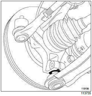
WARNING
Check that the bush is correctly positioned on the lower arm ball joint.
- Refit:
- the engine tie-bar bolt on the gearbox,
- the lower ball joints in the hub carrier,
- the lower ball joint bolts.
- Tighten to torque:
- the engine tie-bar bolt on the gearbox (105 Nm),
- the lower ball joint studs (60 Nm).
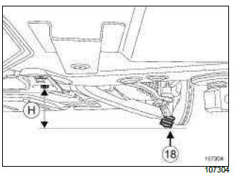
WARNING
When refitting, position the lower arm below the sub-frame rear mounting bolt head (H) = 6 mm to tighten the rubber bushes freely.
- Place the component jack against the subframe rear bolt head.
- Lower the component jack by (H) = 6 mm.
- Rest the lower arm ball joint (18) on the component jack without adjusting the settings.
- In this position, tighten to torque:
- the front bolts mounting the lower arm on the subframe (70 Nm)
- the rear bolt mounting the lower arm on the subframe (105 Nm).
- Remove the component jack.
WARNING
A shim 10 mm thick must be placed between the radiator cross member and the sub-frame. Centre the pin of the radiator cross member in the sub-frame opening at the level of the front lower arm mounting, to torque tighten the radiator cross member mountings.
- Refit the radiator cross member with 10 mm shims.
- Torque tighten the radiator cross member bolts (105 Nm).
- Refit:
- the ball joints and the nuts of the anti-roll bar link rod upper ball joints,
- the ball joints and the track rod end nuts.
- Clip:
- the wheel speed sensors,
- the xenon bulb position sensor tie-rod (if fitted to the vehicle).
- Tighten to torque:
- the anti-roll bar linkage ball joint nuts (44 Nm),
- the track rod end nuts (35 Nm).
- Refit:
- the lower bolts on the bumper,
- the side reinforcement lower bolts,
- the engine undertray,
- the wheel arch protectors (see Front wheel arch liner: Removal - Refitting) (55A, Exterior protection),
- the new bolt and new nut of the universal joint.
- Set the wheels straight ahead.
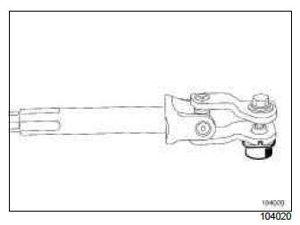
- Ensure that the universal joint nut and bolt are fitted the right way round.
WARNING
Do not separate the two sliding parts of the intermediate shaft.
- Refit:
- the universal joint,
- the new universal joint bolt,
- the new universal joint nut.
- Pretighten the universal joint nut and bolt.
- Pull the intermediate shaft to make sure that the bolt is present in the neck.
- Tighten to torque:
- the side stiffener bolts (21 Nm),
- the universal bolt joints (24 Nm).
- Refit the floor carpet.
Note: Check that the floor carpet fits under the accelerator pedal end-stop.
III - FINAL OPERATION.
- Remove the safety strap(s) from the cooling radiator between the cooling radiator top hose and the bonnet opening striker panel.
- Refit the front wheels (see 35A, Wheels and tyres, Wheel: Removal - Refitting, 35A-1).
- Check the values of the axle assemblies (see 30A, General information, Front axle assembly: Adjustment values, 30A-18).
- It is essential to initialise the discharge bulb system (if fitted to the vehicle) (see Fault finding - Configuration and programming (80B, Headlights).
EQUIPMENT LEVEL EAC or EQUIPMENT LEVEL SPORT
REMOVAL
I - REMOVAL PREPARATION OPERATION
- Position the vehicle on a two-post lift (see Vehicle: Towing and lifting) (02A, Lifting equipment).
- Remove the front wheels (see 35A, Wheels and tyres, Wheel: Removal - Refitting, 35A-1).
- Attach the cooling radiator by the radiator top hose and the bonnet opening striker plate.
- Remove the radiator mounting cross member (see Radiator mounting cross member: Removal - Refitting) (41A, Front lower structure).
II - OPERATION FOR REMOVAL OF PART CONCERNED
- Lift the floor carpet to access the universal joint bolt.
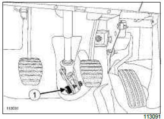
- Remove the universal joint cover (1) (do not keep).
- Set the wheels straight ahead.
- Position the flywheel immobiliser.
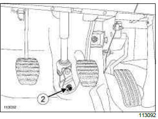
- Remove the universal joint bolt (2) (do not keep),
WARNING
Swivel the universal joint to detach it from the sprocket; do not pull out the intermediate shaft.
- Remove the universal joint from the steering rack.
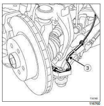
- Unclip the wheel speed sensor wiring (3).
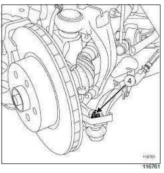
- Remove the track rod end nuts (4).
- Extract the track rod ends using the (Tav. 476).
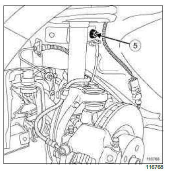
- Remove the anti-roll bar return tie-rod upper ball joint nuts (5).
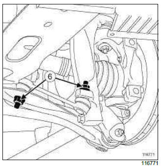
- Remove the nuts (6).
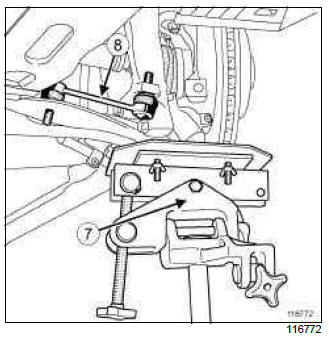
- Engage the driveshafts using the component jack (7).
- Remove the linkages (8).
- Remove the component jack.
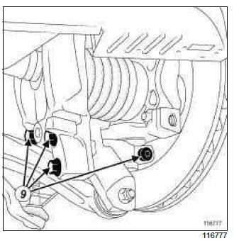
- Remove the bolts (9) between the lower arms and the hub carriers.
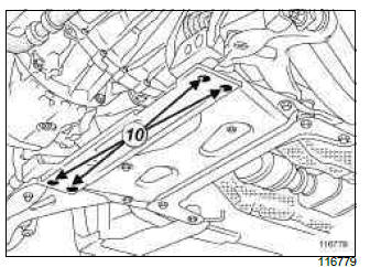
- Remove:
- the sub-frame stiffener nuts (10),
- the sub-frame stiffener.
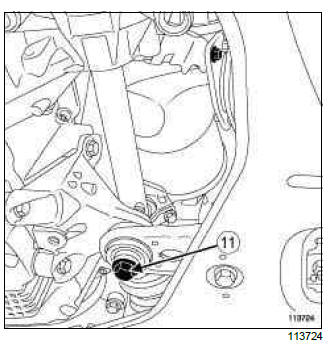
- Remove the engine tie-bar bolt (11).
- Place a component jack under the sub-frame.
- Strap the sub-frame onto the component jack.
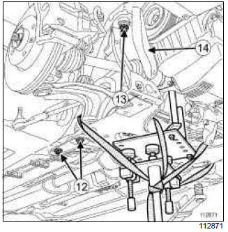
- Remove:
- the rear cross member bolts (12),
- the rear cross member,
- the subframe bolts (13) on the body,
- the side reinforcements (14).
- Lower the sub-frame by approximately 5 cm using the component jack.
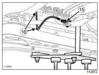
- Disconnect the oxygen sensor connector (15).
- Unclip the wiring (16) from the oxygen sensor.
- Disconnect the connector from the discharge bulb position sensor.
- Unclip the wiring from the discharge bulb position sensor.
- Remove the sub-frame.
- Remove the subframe fittings.
REFITTING
I - REFITTING PREPARATION OPERATION
- Always replace:
- the anti-roll bar tie-bar brake nuts,
- the universal joint bolt and cam nut.
- Degrease the contact surface areas of the subframe and the body using SURFACE CLEANER (see Vehicle: Parts and consumables for the repair) (04B, Consumables - Products).
II - REFITTING OPERATION FOR PART CONCERNED
- Refit the subframe equipment.
- Offer up the sub-frame using an component jack.
- Clip the wiring onto the discharge bulb position sensor.
- Connect the connector to the discharge bulb position sensor.
- Clip the wiring onto the oxygen sensor.
- Connect the oxygen sensor connector.
- Fit the sub-frame to the body.
- Refit:
- the side stiffeners,
- the sub-frame bolts on the body,
- the rear cross member,
- the rear cross member bolts.
- Tighten to torque and in order:
- the sub-frame linkage bolt (105 Nm),
- the rear cross member bolt (105 Nm),
- the bolts to the subframe tie-rod (105 Nm).
- Remove the safety strap(s) and the component jack.
- Refit the engine tie-bar bolt.
- Torque tighten the bolts securing the engine tie-bar on the gearbox (105 Nm).
- Refit:
- the sub-frame stiffener,
- the sub-frame stiffener nuts.
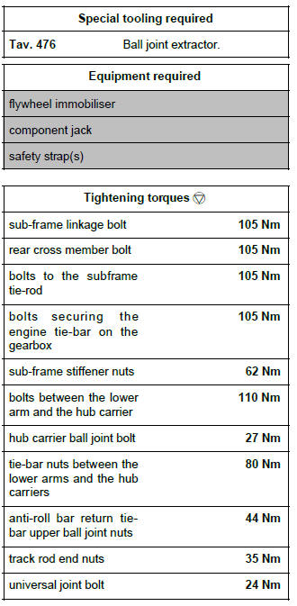
- Torque tighten the sub-frame stiffener nuts (62 Nm).
- Refit the bolts between the lower arms and the hub carriers.
- Tighten to torque:
- the bolts between the lower arm and the hub carrier (110 Nm),
- the hub carrier ball joint bolt (27 Nm).
- Engage the driveshafts using the component jack.
- Refit the linkages between the lower arms and the hub carriers.
- Remove the component jack.
- Refit the tie-bar nuts between the lower arms and the hub carriers.
- Torque tighten the tie-bar nuts between the lower arms and the hub carriers (80 Nm).
- Refit the anti-roll bar return tie-bar upper ball joint nut.
- Torque tighten the anti-roll bar return tie-bar upper ball joint nuts (44 Nm).
- Refit the track rod ends.
- Torque tighten the track rod end nuts (35 Nm).
- Clip the wiring onto the wheel speed sensors.
- Refit:
- the universal joint,
- the new universal joint bolt,
- the new universal joint nut.
- Pretighten the universal joint nut and bolt.
- Pull the intermediate shaft to make sure that the bolt is present in the neck.
- Torque tighten the universal joint bolt (24 Nm).
- Refit the floor carpet.
Note: Check that the floor carpet reaches under the accelerator pedal end-stop.
III - FINAL OPERATION.
- Refit the radiator mounting cross member (see Radiator mounting cross member: Removal - Refitting) (41A, Front lower structure).
- Detach the radiator by the radiator top hose and the bonnet opening striker plate.
- Refit the front wheels (see 35A, Wheels and tyres, Wheel: Removal - Refitting, 35A-1).
- Check the front axle geometry values (see 30A, General information, Front axle system: Adjustment, 30A-23).
- It is essential to initialise the discharge bulb system (see Fault finding - Configuration and programming) (80B, Headlights).

