Renault Clio: Fuses
Fuses: List and location of components
- Passenger compartment fuse and relay box
- Consumer cut-out fuse
- Additional relay/fuse box
- Battery protection fuses
- Protection and switching unit
- Power supply fuse board
- Optional relay unit
I - PASSENGER COMPARTMENT FUSE AND RELAY BOX
LEFT-HAND DRIVE
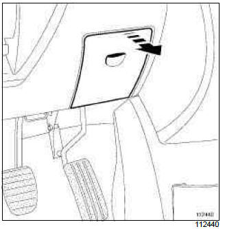
Open the access flap to gain access to the unit.

RIGHT-HAND DRIVE
Open the access flap to gain access to the unit.
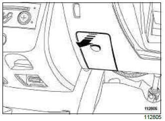
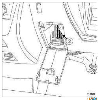
II - CONSUMER CUT-OUT FUSE
LEFT-HAND DRIVE
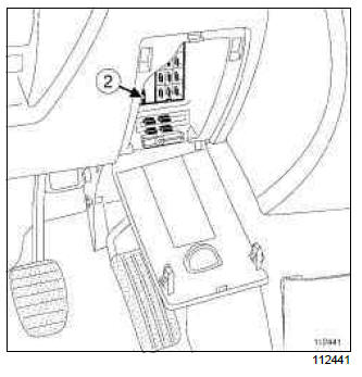
RIGHT-HAND DRIVE
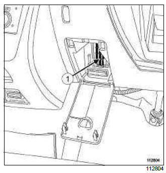
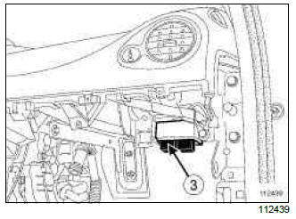
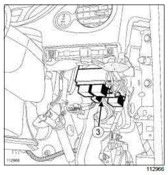
III - ADDITIONAL FUSE AND RELAY BOX
LEFT-HAND DRIVE
Remove the glovebox (see Glovebox: Removal - Refitting) (MR 393, 57A, Interior equipment) to access the box.
RIGHT-HAND DRIVE
Remove the lower dashboard trim (see Dashboard: Removal - Refitting) (MR 393, 57A, Interior equipment) to access the box.
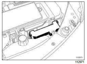
IV - BATTERY PROTECTION FUSES
This box is located on the positive battery terminal.
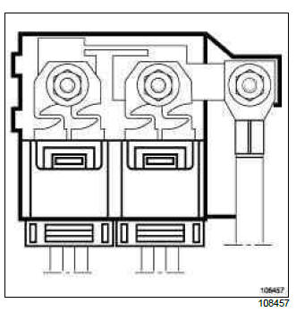
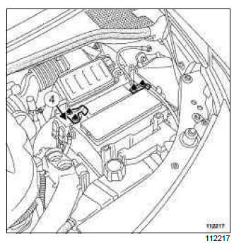
V - PROTECTION AND SWITCHING UNIT
This box is located in the engine compartment, behind the left headlamp.
Remove the cover to gain access to the unit.
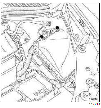
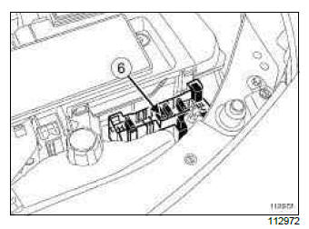
VI - POWER SUPPLY FUSE BOARD
This box is located on the front panel of the battery tray.
Remove the cover to gain access to the unit.
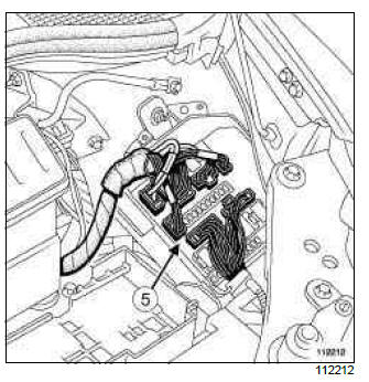
VII - OPTIONAL RELAY UNIT
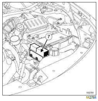
This box is located on the engine-side panel of the battery tray.
Remove the cover to gain access to the unit.
READ NEXT:
 Immobiliser system: List and location of components
I - LIST OF COMPONENTS
II - LOCATION OF COMPONENTS
VEHICLE WITH KEY
1 - Antenna/Transponder ring
2 - Ignition switch
3 - UCH
4 - Key
VEHICLE WITH CARD
5 - Front starting aerial
6 - Central start
Ignition switch: Removal - Refitting
REMOVAL
I - REMOVAL PREPARATION OPERATION
Disconnect the battery (see 80A, Battery, Battery:
Removal - Refitting, 80A-1).
Unclip trim (1).
Remove:
the plastic rivet (2),
bolt (3).
SEE MORE:
Ashtray, cigarette lighter
Cigarette lighter 1
With the ignition on, push in the cigarette
lighter 1. It will spring back with a
click when it is ready. Pull it out to use.
After use, replace it without pushing it
all the way in.
Ashtray
It can be housed in either position 2
or 3.
If your vehicle is
Rear bench seat: functions
Position for use
Raise the headrest as far as possible to
use it in the high position. Check that it
is correctly locked.
Storage position
Press button A and lower the headrest
completely.
When the headrest is set at the
lowest position, this is for storage
only. It should not be in t
