Renault Clio: M4R, and TL4
REMOVAL
I - REMOVAL PREPARATION OPERATION
- Position the vehicle on a two-post lift (see Vehicle: Towing and lifting) (02A, Lifting equipment).
- Remove the front engine cover.
- Disconnect the battery (see Battery: Removal - Refitting) (80A, Battery).
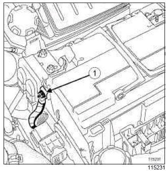
- Remove:
- the nut (1) from the protective fuse mounting wiring,
- the protective fuse mounting wiring,
- the battery (see Battery: Removal - Refitting) (80A, Battery).
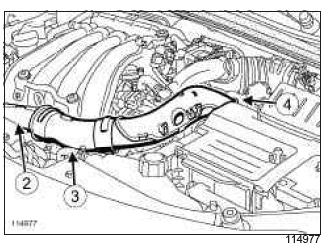
- Disconnect the air filter unit air inlet pipe:
- from the front end panel at (2),
- from the air resonator on the front end panel at (3),
- from the air filter unit at (4).
- Remove the air pipe at the air filter unit inlet.
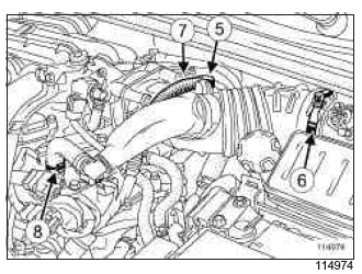
- Unclip the wiring from the air filter unit air outlet pipe at (5).
- Undo the clips on the air filter unit air outlet pipe:
- on the air flow sensor (6),
- on the motorised throttle valve (7).
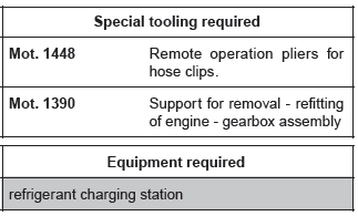
- Separate the clip (8) of the oil vapour rebreathing hose on the rocker cover using the tool (Mot. 1448).
- Disconnect the oil vapour rebreathing hose on the rocker cover.
- Remove the air outlet pipe from the air filter box.
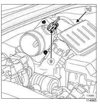
- Disconnect the air flowmeter connector (9).
- Unclip the air flowmeter connector wiring (10).
- Remove the engine undertray.
- Drain:
- the cooling system (see 19A, Cooling, Cooling system: Draining - Refilling, 19A-16),
- the manual gearbox (see Manual gearbox oils: Draining - Filling) (21A, Manual gearbox).
- the refrigerant circuit using a refrigerant charging station (see Refrigerant circuit: Draining - Filling) (62A, Air conditioning).
- Remove:
- the front wheels (see Wheel: Removal - Refitting) (35A, Wheels and tyres),
- the front section of the front wheel arch liners (see Front wheel arch liner: Removal - Refitting) (55A, Exterior protection),
- the front bumper (see Front bumper: Removal - Refitting) (55A, Exterior protection),
- the headlights (see Headlight: Removal - Refitting) (80B, Headlights),
- the front impact cross member (see Front impact cross member: Removal - Refitting) (41A, Front lower structure),
- the front end panel air resonator (see 12A, Fuel mixture, Air resonator: Removal - Refitting, 12A-10).
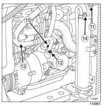
- Remove:
- the bolt (11) from the compressor-condenser connecting pipe, on the condenser,
- the bolt (12) from the compressor-condenser connecting pipe, on the compressor,
- the compressor-condenser connecting pipe (13),
- the bolt (14) from the dehydrator reservoir-expansion valve connecting pipe on the dehydrator reservoir.
- Disconnect the dehydrator reservoir-expansion valve connecting pipe on the dehydrator reservoir.
- Remove the bolt (15) from the compressor-intermediate pipe connecting pipe on the compressor.
- Disconnect the compressor-intermediate pipe connecting pipe on the compressor.
WARNING
Plugs must be fitted on the hoses to prevent moisture from entering the system.
- Remove:
- the radiator mounting cross member (see Radiator mounting cross member: Removal - Refitting) (41A, Front lower structure),
- the radiator (see 19A, Cooling, Cooling radiator: Removal - Refitting, 19A-20),
- the front left-hand wheel driveshaft (see Front left-hand driveshaft: Removal - Refitting) (29A, Driveshafts),
- the front right-hand wheel driveshaft (see Front right-hand driveshaft: Removal - Refitting) (29A, Driveshafts).
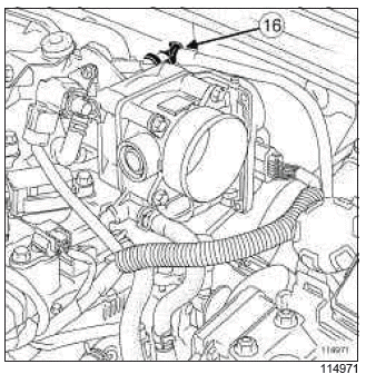
- Disconnect the brake servo pipe union (16) from the inlet distributor.
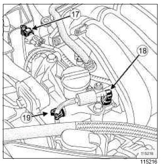
- Disconnect: - the petrol vapour rebreather pipe (17), - the fuel supply pipe (18).
WARNING
Protect sensitive areas from fuel spillage.
- Unclip the fuel supply pipe at (19).
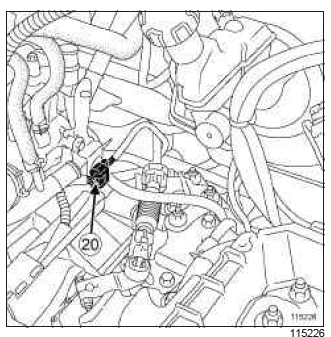
- Disconnect the upstream oxygen sensor connector (20).
- Move the connector away from the upstream oxygen sensor.
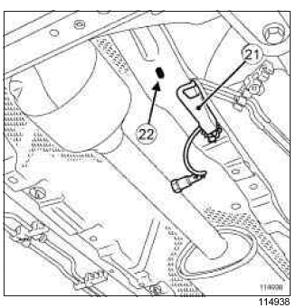
- Remove the plastic cover (21).
- Detach the downstream oxygen sensor connector at (22).
- Disconnect the downstream oxygen sensor connector.
- Unclip the downstream oxygen sensor wiring from the power-assisted steering box.
- Feed the downstream oxygen sensor wiring into the engine compartment.
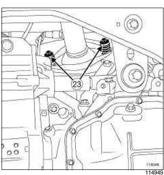
- Remove:
- the bolts (23) from the exhaust flange,
- the exhaust flange seal.
- Remove the rear suspended engine mounting (see 19D, Engine mounting, Lower engine tie-bar: Removal - Refitting, 19D-13).
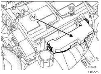
- Remove the cover (24) from power supply fuse unit.
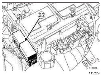
- Unclip the optional relay unit (25).
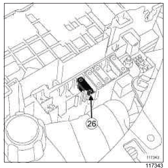
- Remove the fuse (26).
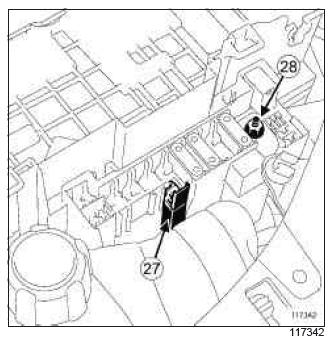
- Unclip the fuse holder (27).
- Remove the nut (28) from the supply wiring of the power supply fuse unit.
- Disconnect the supply wiring from the power supply fuse unit.
- Remove the battery tray (see Battery tray: Removal - Refitting) (80A, Battery).
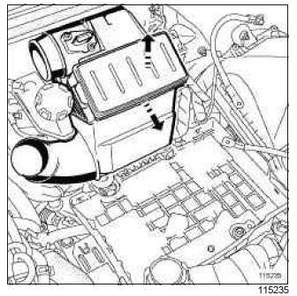
- Remove the air filter unit in the direction of the arrows.
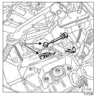
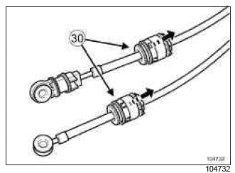
- Unclip:
- the control cables (29) on the gearbox using an open-ended spanner,
- the control cable sleeve stops (30) on the gearbox.
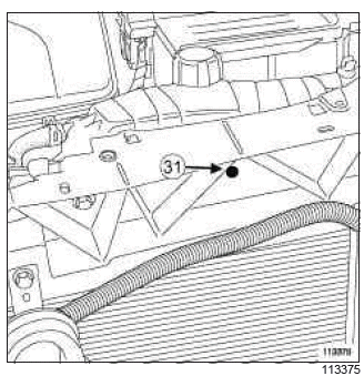
- Remove the clip (31) from the expansion bottle.
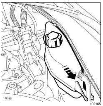
- Move the expansion bottle away from its housing in the direction of the arrow.
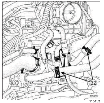
- Separate the clips (32) on the passenger compartment heater hoses using the tool (Mot. 1448).
- Disconnect the passenger compartment heater hoses.
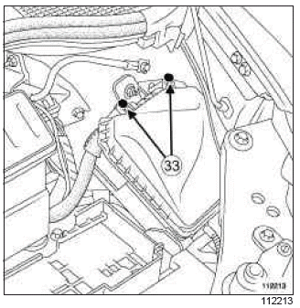
- Remove:
- the bolts (33) from the Protection and Switching Unit cover,
- the Protection and Switching Unit cover.
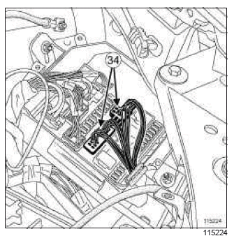
- Disconnect the engine wiring connectors (34) from the Protection and Switching Unit.
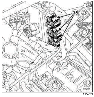
- Disconnect the injection computer connectors (35).
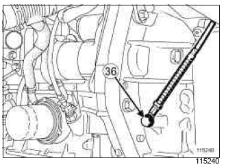
- Remove:
- the bolt (36) from the manual gearbox earth wiring.
- the manual gearbox earth wiring.
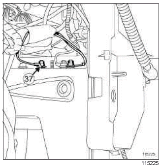
- Remove the nut (37) from the side member earth wiring.
- Move the earth wiring away from the side member.
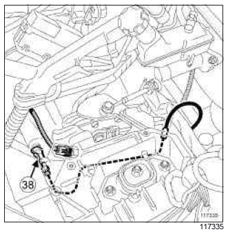
- Push on the clip of the hydraulic clutch control pipe.
- Disconnect the hydraulic clutch control pipe (38).
- Unclip the hydraulic clutch control pipe.
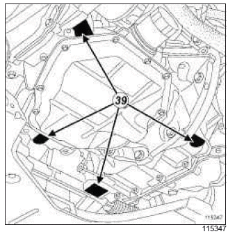
- Support the (Mot. 1390) on the " engine - gearbox " assembly marks.
II - OPERATION FOR REMOVAL OF PART CONCERNED
- Remove the right-hand suspended engine mounting (see 19D, Engine mounting, Right-hand suspended engine mounting: Removal - Refitting, 19D-22).
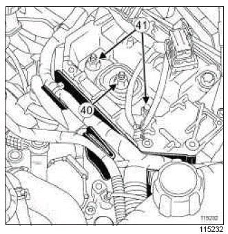
- Separate the neck of the electrical wiring from the gearbox support.
- Remove:
- the left-hand suspended engine mounting shaft nut (40),
- the nuts (41) from the left-hand suspended engine mounting rubber pad,
- the left-hand suspended engine mounting rubber pad.
Note: Tap the bolt with a copper hammer, if necessary.
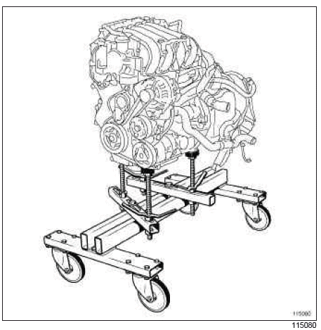
- Remove the " engine and gearbox " assembly.
REFITTING
I - REFITTING PREPARATION OPERATION
- For standard engine replacements (see Engine: New replacement) (Technical Note 6020A, 10A, Engine and peripherals).
- parts always to be replaced: seal between catalytic converter and exhaust downpipe hose
II - REFITTING OPERATION FOR PART CONCERNED
- Position the " engine - gearbox " assembly in the body.
- Refit:
- the left-hand suspended engine mounting rubber pad,
- the nuts for the left-hand suspended engine mounting rubber pad,
- the left-hand suspended engine mounting shaft nut.
- Torque tighten (see 19D, Engine mounting, Suspended engine mounting: Tightening torque, 19D-1).
- Refit the right-hand suspended engine mounting (see 19D, Engine mounting, Right-hand suspended engine mounting: Removal - Refitting, 19D-22).
- Lift the (Mot. 1390) from the " engine - gearbox " assembly.
III - FINAL OPERATION
- Connect the hydraulic clutch control pipe.
- Clip on the hydraulic clutch control pipe.
- Fit the side member earth wiring.
- Refit the side member earth wiring nuts.
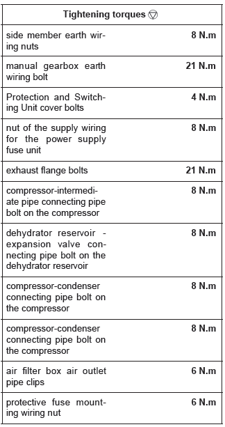
- Torque tighten the side member earth wiring nuts (8 N.m).
- Refit:
- the manual gearbox earth wiring,
- the bolt to the manual gearbox earth wiring.
- Torque tighten the manual gearbox earth wiring bolt (21 N.m).
- Connect:
- the injection computer connectors,
- the engine wiring connectors to the Protection and Switching Unit.
- Refit:
- the Protection and Switching Unit cover,
- the bolts on the Protection and Switching Unit cover.
- Torque tighten the Protection and Switching Unit cover bolts (4 N.m).
- Connect the passenger compartment heater hoses.
- Fit:
- the passenger compartment heater hose clips,
- the expansion bottle into its housing.
- Refit the clip to the expansion bottle.
- Clip:
- the control cables onto the gearbox using an open-ended spanner,
- the gearbox control cable sleeve stops onto the gearbox.
- Refit:
- the battery tray (see Battery tray: Removal - Refitting) (80A, Battery),
- the air filter unit.
- Connect the air flowmeter connector.
- Clip on the air flowmeter connector wiring.
- Connect the supply wiring of the power supply fuse unit.
- Refit the nut of the supply wiring for the power supply fuse unit.
- Torque tighten the nut of the supply wiring for the power supply fuse unit (8 N.m).
- Clip in the fuse holder.
- Refit:
- the fuse,
- the cover of the power supply fuse unit.
- Clip on the optional relay unit.
- Refit the rear suspended engine mounting (see 19D, Engine mounting, Lower engine tie-bar: Removal - Refitting, 19D-13).
- Tighten to torque the (see 19D, Engine mounting, Suspended engine mounting: Tightening torque, 19D-1)
- Refit:
- a new exhaust flange seal,
- the exhaust flange bolts.
- Torque tighten the exhaust flange bolts (21 N.m).
- Clip the downstream oxygen sensor wiring onto the power-assisted steering box.
- Connect the downstream oxygen sensor connector.
- Clip the downstream oxygen sensor connector.
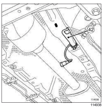
- Refit the plastic cover (42).
- Connect:
- the upstream oxygen sensor connector,
- the brake servo pipe to the brake servo,
- the petrol vapour rebreathing pipe,
- the fuel supply pipe.
- Clip on the fuel supply pipe.
- Refit:
- the front right-hand wheel driveshaft (see Front right-hand driveshaft: Removal - Refitting) (29A, Driveshafts),
- the front left-hand wheel driveshaft (see Front left-hand driveshaft: Removal - Refitting) (29A, Driveshafts),
- the radiator (see 19A, Cooling, Cooling radiator: Removal - Refitting, 19A-20),
- the radiator mounting cross member (see Radiator mounting cross member: Removal - Refitting) (41A, Front lower structure),
- the air conditioning pipes,
- the air conditioning pipe bolts.
- Connect the compressor-intermediate pipe connecting pipe on the compressor.
- Refit the bolt to the compressor-intermediate pipe connecting pipe on the compressor.
- Torque tighten the compressor-intermediate pipe connecting pipe bolt on the compressor (8 N.m).
- Connect the dehydrator reservoir-expansion valve connecting pipe on the dehydrator reservoir.
- Refit the dehydrator reservoir-expansion valve connecting pipe bolt on the dehydrator reservoir.
- Torque tighten the dehydrator reservoir - expansion valve connecting pipe bolt on the dehydrator reservoir (8 N.m).
- Refit:
- the compressor-condenser connecting pipe,
- the condenser-compressor connecting pipe bolt on the compressor,
- the compressor-condenser connecting pipe bolt on the condenser.
- Tighten to torque:
- the compressor-condenser connecting pipe bolt on the compressor (8 N.m),
- the compressor-condenser connecting pipe bolt on the compressor (8 N.m).
- Refit:
- the front end panel air resonator (see 12A, Fuel mixture, Air resonator: Removal - Refitting, 12A-10),
- the front impact cross member (see Front impact cross member: Removal - Refitting) (41A, Front lower structure),
- the headlights (see Headlight: Removal - Refitting) (80B, Headlights),
- the front bumper (see Front bumper: Removal - Refitting) (55A, Exterior protection),
- the front section of the front wheel arch liners (see Front wheel arch liner: Removal - Refitting) (55A, Exterior protection),
- the front wheels (see Wheel: Removal - Refitting) (35A, Wheels and tyres).
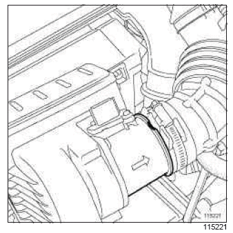
- Refit the air filter unit air outlet pipe on the air flowmeter, taking care to follow the markings for fitting.
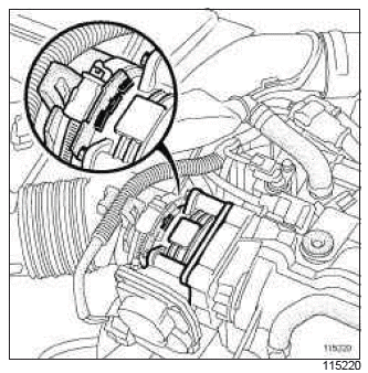
- Refit the air filter unit air outlet pipe on the motorised throttle valve, taking care to follow the markings for fitting.
- Connect the oil vapour rebreathing hose on the rocker cover.
- Fit the oil vapour rebreathing hose clip onto the rocker cover using the tool (Mot. 1448).
- Torque tighten the air filter box air outlet pipe clips (6 N.m).
- Refit:
- the battery (see Battery: Removal - Refitting) (80A, Battery),
- the protective fuse mounting wiring,
- the protective fuse mounting cable nut.
- Torque tighten the protective fuse mounting wiring nut (6 N.m).
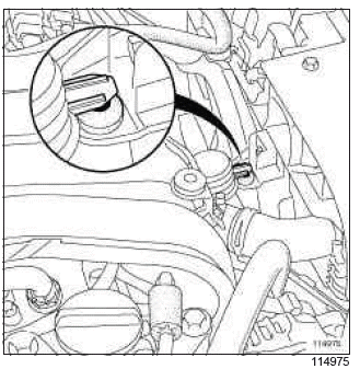
- Before refitting the air filter unit air inlet pipe, check that the upper mounting of the air resonator is correctly clipped on the front end panel.
- Refit the air filter unit air inlet pipe.
- Connect the air filter unit air inlet pipe:
- to the front end panel,
- on the air resonator on the front end panel,
- on the air filter box.
- Connect the battery (see Battery: Removal - Refitting) (80A, Battery).
- Perform the following operations:
- fill the manual gearbox (see Manual gearbox oils: Draining - Filling) (21A, Manual gearbox),
- fill the refrigerant circuit using a refrigerant charging station (see Refrigerant circuit: Draining - Filling) (62A, Air conditioning),
- fill and bleed the cooling circuit (see 19A, Cooling, Cooling system: Draining - Refilling, 19A- 16),
- bleed the clutch circuit (see Clutch circuit: Bleed) (37A, Mechanical component controls).
- Refit:
- the engine cover,
- the engine undertray.
- Connect the battery (see Battery: Removal - Refitting) (80A, Battery).
READ NEXT:
 K9K, and JA5
REMOVAL
I - REMOVAL PREPARATION OPERATION
Position the vehicle on a two-post lift (see Vehicle:
Towing and lifting) (02A, Lifting equipment).
Remove the front engine cover.
Disconnect the batte
 D4F, and JA3
REMOVAL
I - REMOVAL PREPARATION OPERATION
Position the vehicle on a two-post lift (see Vehicle:
Towing and lifting) (MR 392, 02A, Lifting equipment).
Remove:
the air filter box (see 12A, Fuel m
 D4F, and 784 or 786
REMOVAL
I - REMOVAL PREPARATION OPERATION
Position the vehicle on a two-post lift (see Vehicle:
Towing and lifting) (MR 392, 02A, Lifting equipment).
Remove:
the engine cover,
the engine unde
SEE MORE:
 Front side door protective strip: Removal - Refitting
REMOVAL
I - REMOVAL PREPARATION OPERATION
Unclip the blanking cover (1).
Remove the bolt.
Remove the side mounted indicator (2) using a small
flat screwdriver.
Disconnect the power supply connector.
II - REMOVAL OPERATION FOR PART
CONCERNED
Slide the door rubbing strip towards the rear
 Dashboard: Removal - Refitting
IMPORTANT
To avoid all risk of damage to the systems, apply
the safety and cleanliness instructions and operation
recommendations before carrying out any
repair:
(see Airbag and pretensioners: Precautions
for the repair) (88C, Airbag and pretensioners),
(see Vehicle: Precautions for the repair)
© 2016-2026 Copyright Renault Clio Owners Club

