Renault Clio: Oil vapour rebreathing circuit: Descriptions
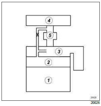
K4J or K4M, and 780 or 800 or 801
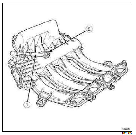
- Oil vapour rebreathing duct
- Calibrated port
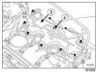
- Oil vapour recovery plate located on the rocker cover
- Oil vapour rebreathing hole
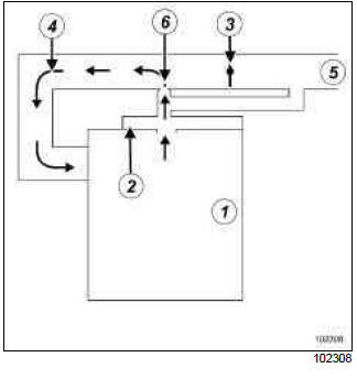
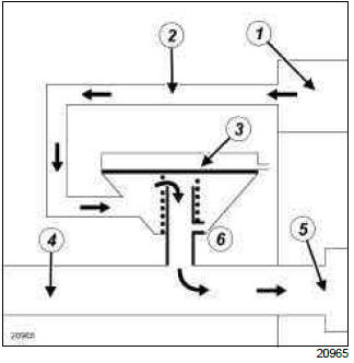
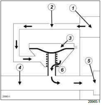
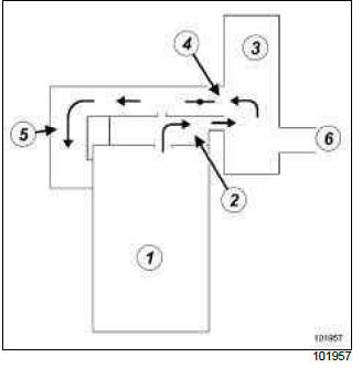
Oil vapour rebreathing circuit: Operating diagram
K4J, and 780 - K4M, and 800 or 801
A: under low loads, the oil vapours are rebreathed in small quantities through the calibrated orifice (6).
B: under medium and heavy loads, the oil vapours are rebreathed in large quantities through the valve
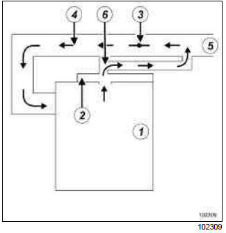
- Engine
- Oil vapour recovery plate
- Motorised throttle valve
- Inlet manifold
- Air inlet
- Calibrated choke
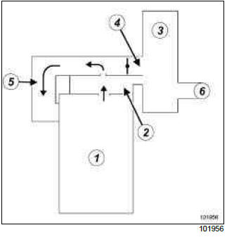
D4F
The oil decanter is located in the rocker cover.
These two components are manufactured together.
- Engine
- Rocker cover
- Inlet manifold
- Air filter unit
- Motorised throttle valve
K9K, and 750 or 752 or 764 or 766 or 768
A: Low load
B: Medium and high loads
- Rocker cover
- Oil vapour rebreathing duct
- Oil vapour rebreathing valve
- Air inlet duct
- Turbocharger
- Atmospheric pressure
A: At low load, the vacuum pressure prevailing in the air inlet duct is below the spring calibration. Large quantities of oil vapour are sucked back in by the vacuum prevailing in the air inlet duct.
B: At medium or high load, the vacuum pressure prevailing in the air inlet duct pulls the valve diaphragm, small quantities of oil vapour are rebreathed in via a calibrated jet.
F4R, and 830
Operating diagram of the oil vapour rebreathing circuit for average and high loads
Operating diagram of the oil vapour rebreathing circuit for low loads
- Engine
- Oil separator
- Air filter unit
- Throttle valve
- Inlet manifold
- Air inlet
READ NEXT:
 Charge circuit: Specifications
D4F or F4R or K4J or K4M or K9K or M4R
ALTERNATOR SPECIFICATIONS
Charge circuit: Function
D4F or F4R or K4J or K4M or K9K or M4R
OPERATION
These vehicles are fitted with a built-in regulator and an
i
Alternator: Removal - Refitting
K4J, and STANDARD HEATING - K4M, and STANDARD HEATING
REMOVAL
I - REMOVAL PREPARATION OPERATION
Position the vehicle on a two-post lift (see Vehicle: Towing and
lifting).
Remove the air inlet
SEE MORE:
Driving
The Renault Clio IV (2014-2019) offers a satisfying driving experience with its nimble handling and responsive performance. Its compact size and maneuverability make it well-suited for urban driving and tight parking spaces. The precise steering and suspension tuning provide a balanced and confident
Your comfort
The Renault Clio IV (2014-2019) is designed with your comfort in mind. It features a well-crafted interior with quality materials and thoughtful ergonomics. The seats offer excellent support and adjustability, providing a comfortable driving experience. The cabin is designed to minimize noise and vi
