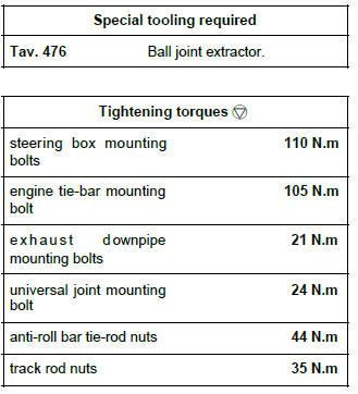
Renault Clio: Power Assisted Steering
Power-assisted steering: Function
Assistance varies according to vehicle speed.
IMPORTANT
Do not remove any steering column component.
Note: During fault finding, the Service warning light flashes at a frequency of 2 Hz.
Power-assisted steering box: List and location of components
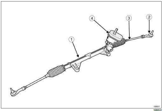
- Steering rack
- Track rod
- Axial ball joint linkage
- Bulkhead seal
Power-assisted steering box: Removal - Refitting
JH3 or JR5, and LEFT-HAND DRIVE
REMOVAL
I - REMOVAL PREPARATION OPERATION
- Position the vehicle on a two-post lift (see Vehicle: Towing and lifting) (MR 392, 02A, Lifting equipment).
- Remove:
- the front wheels (see 35A, Wheels and tyres, Wheel: Removal - Refitting, 35A-1),
- the engine undertray.
II - OPERATION FOR REMOVAL OF PART CONCERNED
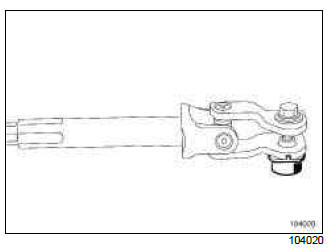
- Lift the floor carpet to access the universal joint bolt.
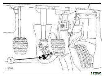
- Remove the universal joint cover (1) (do not keep).
- Set the wheels straight ahead.
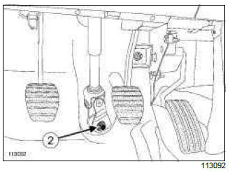
- Remove the universal joint bolt (2) (do not keep),
- Remove the universal joint from the steering box.
- Remove:
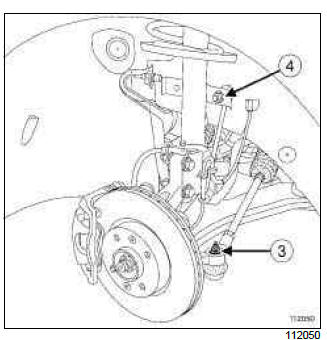
- the mounting nuts (3) from the track rod,
- the anti-roll bar tie-bar upper nuts (4).
Note: It is necessary to rotate the anti-roll bar onto itself in order to make it easier to position the steering rack on the sub-frame cross member.
- Extract the ball joint using (1) Tav. 476.
- Tilt the anti-roll bar towards the rear of the vehicle.
- Unclip the oxygen sensor wiring harness from the steering rack.
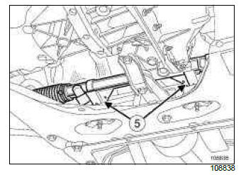
- Remove the steering box mountings (5).
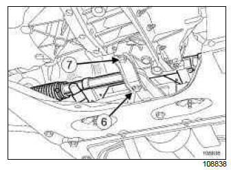
- Remove the engine tie-bar mounting (6) on the engine.
- Loosen the engine tie-bar retaining bracket mounting bolt (7) in order to be able to turn the retaining bracket.
- Tip the engine forwards using a lever to remove the steering rack.
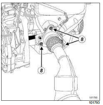
- Remove the exhaust downpipe mounting bolts (8), if necessary.
- Remove the steering rack, going towards the left-hand
side of the vehicle; two people are required to
carry out this operation.
If the vehicle is fitted with xenon bulbs, be careful not to damage the xenon bulb sensor.
REFITTING
I - REFITTING PREPARATION OPERATION
- Always replace the following after each removal
operation:
- the universal joint nut and bolt,
- the anti-roll bar link rod brake nuts.
II - REFITTING OPERATION FOR PART CONCERNED
- Refit:
- the steering rack inserting it from the left-hand side of the vehicle, being careful not to damage the xenon bulb beam sensor,
- the xenon bulb beam sensor (if fitted to the vehicle),
- the steering rack mounting bolts.
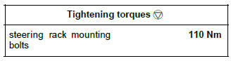
- Torque tighten the steering box mounting bolts (110 N.m), starting with the bolt on the right-hand side of the vehicle.
- Refit the engine tie-bar mountings.
- Torque tighten the engine tie-bar mounting bolt (105 N.m).
- Refit the exhaust downpipe mounting bolts, if they were removed.
- Respect the direction when fitting the universal joint nut and bolt.
- Refit:
- the universal joint,
- the new universal joint bolt,
- the new universal joint nut.
- Pre-tighten the universal joint nut and bolt.
- Pull the intermediate shaft to make sure that the bolt is present in the neck.
- Tighten to torque:
- the exhaust downpipe mounting bolts (21 N.m),
- the universal joint mounting bolt (24 N.m).
- Refit the floor carpet.
Note: Check that the floor carpet fits under the accelerator pedal end-stop.
- Clip the oxygen sensor wiring harness back onto the steering rack.
- Tilt the anti-roll bar back into its original position.
- Place the ball joints back into their housing.
- Refit:
- the track rod mounting nuts,
- the anti-roll bar link rod lower nuts.
- Tighten to torque:
- the anti-roll bar tie-rod nuts (44 N.m),
- the track rod nuts (35 N.m).
III - FINAL OPERATION
- Refit:
- the engine undertray,
- the front wheels (see 35A, Wheels and tyres, Wheel: Removal - Refitting, 35A-1).
- Adjust the front axle assemblies (see Adjusting the front axle system).
- Be sure to initialise the xenon bulb system (if fitted to the vehicle); (see MR 394 Fault finding, 80C, Discharge bulbs, Replacement of components).
DP0 or TL4, and LEFT-HAND DRIVE
REMOVAL
I - REMOVAL PREPARATION OPERATION
- Put the vehicle on a two-post lift (see Vehicle: Towing and lifting).
- Remove:
- the front wheels (see 35A, Wheels and tyres, Wheel: Removal - Refitting, 35A-1),
- the sub-frame (see 31A, Front axle components, Front axle subframe: Removal - Refitting, 31A-55).
II - OPERATION FOR REMOVAL OF PART CONCERNED
vehicle sub-frame without xenon bulbs
vehicle sub-frame fitted with xenon bulbs
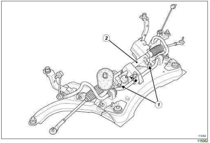
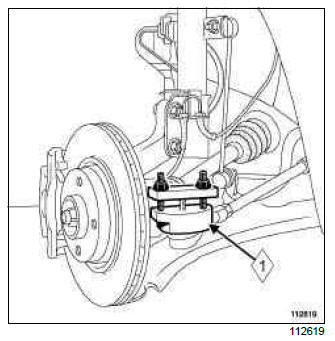
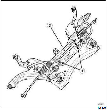
- Remove:
- the steering rack mounting bolts (1),
- the steering rack (2) being careful not to damage the xenon bulb beam sensor.
REFITTING
I - REFITTING PREPARATION OPERATION
- Always replace the following after each removal
operation:
- the anti-roll bar link rod brake nuts,
- the universal joint bolt and cam nut.
WARNING
Be sure to insert a 10 mm shim between the radiator cross member and the sub-frame, and centre the radiator cross member pin in the subframe opening on the lower arm front mounting, to torque tighten the radiator cross member mountings.
- Set the wheels straight ahead.
II - REFITTING OPERATION FOR PART CONCERNED
- Refit:
- the steering rack,
- the xenon bulb beam sensor (if fitted to the vehicle),
- the steering rack mounting bolts.
- Tighten to torque the steering rack mounting bolts (110 Nm).
III - FINAL OPERATION
- Refit:
- the sub-frame (see 31A, Front axle components, Front axle subframe: Removal - Refitting, 31A-55),
- the front wheels (see 35A, Wheels and tyres, Wheel: Removal - Refitting, 35A-1).
- Adjust the front axle assemblies (see Adjusting the front axle system).
- Be sure to initialise the xenon bulb system (if fitted to the vehicle); (see MR 394 Fault finding, 80C, Xenon bulbs, Replacement of components).
Electric power-assisted steering computer: Configuration
- Configure the power-assisted steering computer (see MR 394 Diagnostic, 36B, Electric power assisted steering, Component replacements).
READ NEXT:
 Manual gear control: Adjustment
TL4
ADJUSTMENT
ADJUSTMENT OF SELECTION CABLE DURING A
REMOVAL OPERATION
1 - Passenger compartment
Shift the selector lever to third gear.
Fit a shim (1) (6 mm between the locking ring and
rever
Master cylinder: Removal - Refitting
F4R or K4J or K4M or K9K or M4R, and LEFT-HAND DRIVE
WARNING
Prepare for brake fluid outflow, to prevent damage
to the mechanical parts and bodywork around the
braking system.
REMOVAL
I - REMOVAL PRE
SEE MORE:
Driving
The Renault Clio IV (2014-2019) offers a satisfying driving experience with its nimble handling and responsive performance. Its compact size and maneuverability make it well-suited for urban driving and tight parking spaces. The precise steering and suspension tuning provide a balanced and confident
Your comfort
The Renault Clio IV (2014-2019) is designed with your comfort in mind. It features a well-crafted interior with quality materials and thoughtful ergonomics. The seats offer excellent support and adjustability, providing a comfortable driving experience. The cabin is designed to minimize noise and vi
