Renault Clio: Automatic gearbox: Removal - Refitting
K4M, and DP0
REMOVAL
I - REMOVAL PREPARATION OPERATION
- Position the vehicle on a two-post lift (see Vehicle: Towing and lifting) (02A, Lifting equipment).
- Remove:
- the engine undertray,
- the front wheels (see Wheel: Removal - Refitting) (35A, Wheels and tyres),
- the front wheel arch liners (see Front wheel arch liner: Removal - Refitting) (55A, Exterior protection),
- the battery (see ) (80A, Battery)
- the battery tray (see ) (80A, Battery),
- the front bumper (see Front bumper: Removal - Refitting) (55A, Exterior protection).
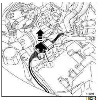
- Disconnect the modular connector by pulling the connector slide mechanism (1).
- Remove:
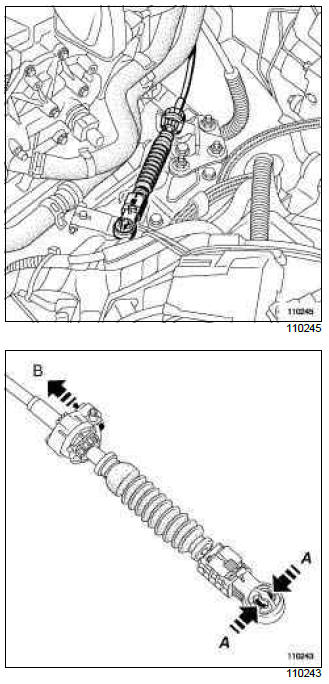
- the multifunction switch control cable by pressing at (A),
- the control cable sheath stop from the gearbox support by pulling the catch at (B).
- Disconnect the crankshaft position sensor connector.
- Remove the crankshaft position sensor.
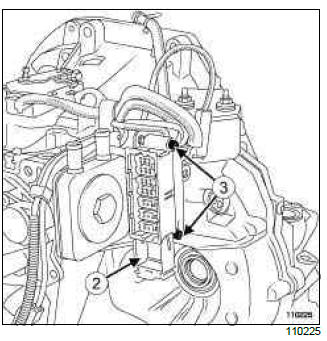
- Disconnect the automatic transmission connector by pulling out the slide (2).
- Remove the bolts (3) from the automatic transmission connector and slide it into a waterproof plastic bag.
Note: Protect the automatic transmission connector by sliding it into a waterproof plastic bag.
- Drain the cooling system (see Cooling system: Draining - Refilling) (19A, Cooling).
- Disconnect the hoses from the expansion bottle.
- Remove the plastic rivet from the expansion bottle.
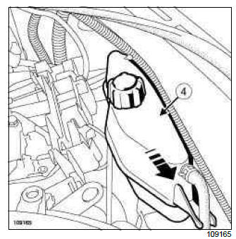
- Remove:
- the expansion bottle (4) in the direction of the arrow,
- the air resonator.
- Disconnect the automatic transmission cooling hoses.
- Remove the bottom cooling hose.
- Unclip the top cooling hose from the thermostat.
- Disconnect:
- the engine cooling fan,
- the engine fan relay unit,
- the pressostat.
- Move the wiring aside.
- Unclip the radiator fan unit.
- Disconnect the anti-lock braking system sensor connectors.
- Remove:
- the left-hand driveshaft (see 29A, Driveshafts, Front left-hand driveshaft: Removal - Refitting, 29A-2),
- the right-hand driveshaft (see 29A, Driveshafts, Front right-hand driveshaft: Removal - Refitting, 29A-9).
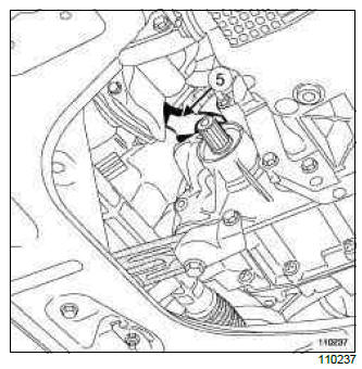
- Remove the catalytic converter stay (5).
- Fit the cooling assembly to the upper cross member using a safety strap(s).
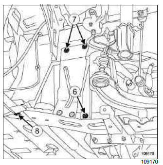
- Remove:
- the tie rod bolts (6),
- the side stiffener bolts (7),
- the bolts (8) on the cooling radiator support cross member,
- the cooling radiator support cross member,
- the fan unit.
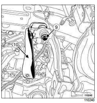
- Loosen the subframe bolt (9).
- Turn the stay (10) towards the rear to free the access to the automatic transmission.
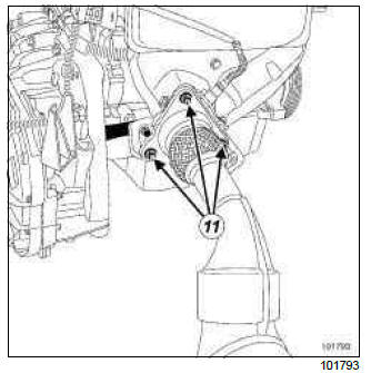
- Remove:
- the exhaust manifold bracket nuts (11),
- the engine tie-bar (see Lower engine tie-bar: Removal - Refitting) (19D, Engine mounting),
- the petrol injection computer (see Petrol injection computer: Removal - Refitting) (17B, Petrol injection).
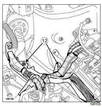
- Remove the wiring channel nuts (12) on the body.
- Attach the wiring channel in order to access the automatic transmission support freely.
- Remove the wiring channel nuts on the engine.
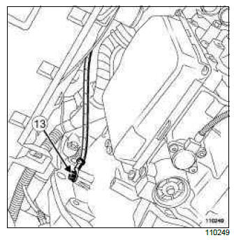
- Remove:
- the bolt (13) on the automatic transmission earth strap,
- the starter (see Starter: Removal - Refitting) (16A, Starting - Charging),
- the converter nuts via the starter aperture.
II - OPERATION FOR REMOVAL OF PART CONCERNED
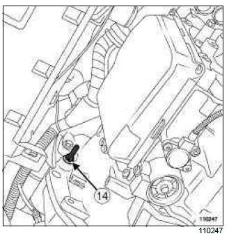
- Remove the upper automatic transmission bell housing stud (14).
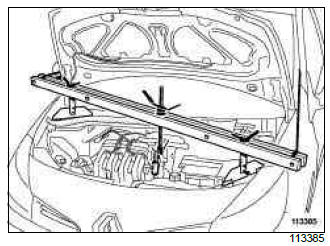
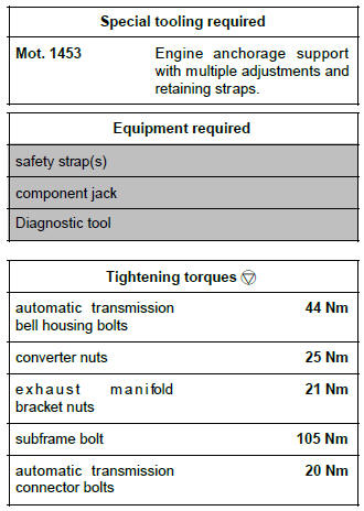
- Fit the tool (Mot. 1453) with its safety strap(s).
- Remove:
- the left-hand suspended engine mounting (see Left-hand suspended engine mounting: Removal - Refitting) (19D, Engine mounting),
- the automatic transmission bell housing upper bolts.
- Fit the component jack beneath the automatic transmission.
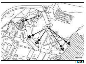
- Remove:
- the lower bolts (15) on the automatic transmission bell housing,
- the automatic transmission lower stud (16),
- the automatic gearbox.
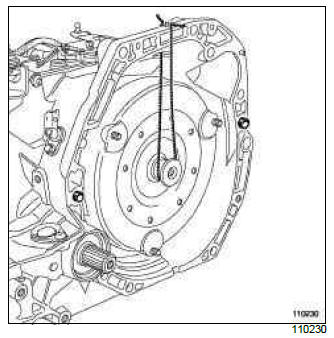
- Attach the converter with string to stop it being detached.
REFITTING
I - REFITTING PREPARATION OPERATION
Note: Do not reuse the converter nuts or the inertia flywheel nuts if they have been removed: always use new nuts.
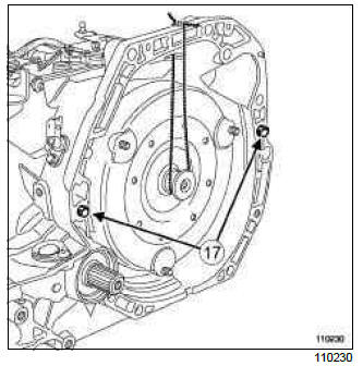
- Check that the centring dowels (17) are in place.
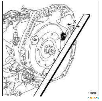
- Check the positioning of the converter in relation to the engine/automatic transmission coupling face using a ruler and a slide; the value should be (X) = 18.22 mm +- 1.
II - REFITTING OPERATION FOR PART CONCERNED
- Refit:
- the automatic gearbox,
- the automatic transmission studs,
- the automatic transmission bell housing lower bolts.
Note: Ensure that the converter is inserted correctly in the input shaft.
III - FINAL OPERATION.
- Remove the tool component jack under the automatic transmission.
- Refit the automatic transmission bell housing upper bolts.
- Torque tighten the automatic transmission bell housing bolts (44 Nm).
- Refit the left-hand suspended engine mounting (see Left-hand suspended engine mounting: Removal - Refitting) (19D, Engine mounting).
- Remove the tool (Mot. 1453) with its safety strap(s).
- Refit the converter nuts via the starter aperture.
- Torque tighten the converter nuts (25 Nm)
- Refit:
- the starter (see Starter: Removal - Refitting) (16A, Starting - Charging),
- the earth strap bolt on the automatic transmission.
- Detach the wiring channel.
- Refit:
- the nuts mounting the wiring channel to the body,
- the petrol injection computer (see Petrol injection computer: Removal - Refitting) (17B, Petrol injection),
- the engine tie-bar (see Lower engine tie-bar: Removal - Refitting) (19D, Engine mounting),
- the exhaust manifold bracket.
- Torque tighten the exhaust manifold bracket nuts (21 Nm).
- Refit the subframe tie-rod.
- Torque tighten the subframe bolt (105 Nm).
- Refit:
- the fan assembly via the underbody of the vehicle,
- the radiator support cross member,
- the radiator support cross member bolts,
- the side stiffener bolts,
- the tie-rod bolts.
- Detach the cooling assembly from the upper cross member.
- Refit:
- the catalytic converter stay,
- the left-hand driveshaft (see 29A, Driveshafts, Front left-hand driveshaft: Removal - Refitting, 29A-2),
- the right-hand driveshaft (see 29A, Driveshafts, Front right-hand driveshaft: Removal - Refitting, 29A-9).
- Connect the ABS sensor connectors.
- Clip on the radiator fan assembly.
- Connect:
- the pressostat,
- the engine fan relay unit,
- the engine cooling fan.
- Fit the thermostat upper cooling hose.
- Refit the lower cooling hose.
- Connect the automatic transmission cooling hoses.
- Refit:
- the air resonator,
- the expansion bottle,
- the plastic rivet of the expansion bottle,
- the front bumper (see Front bumper: Removal - Refitting) (55A, Exterior protection).
- Connect the expansion bottle hoses.
- Fill the cooling system (see Cooling system: Draining - Refilling) (19A, Cooling).
- Take the automatic transmission connector out of the plastic bag.
- Refit the automatic transmission connector.
- Torque tighten the automatic transmission connector bolts (20 Nm).
- Connect the automatic transmission connector by pushing the slide mechanism.
- Refit the crankshaft position sensor.
- Connect the crankshaft position sensor.
- Refit:
- the control cable sheath stop on the automatic transmission mounting,
- the multifunction switch control cable.
- Connect the modular connector by pushing the connector slide mechanism.
- Refit:
- the battery tray (see ) (80A, Battery),
- the battery (see ) (80A, Battery)
- the front wheel arch liners (see Front wheel arch liner: Removal - Refitting) (55A, Exterior protection),
- the front wheels (see Wheel: Removal - Refitting) (35A, Wheels and tyres),
- the engine undertray.
- Connect the battery (see Battery: Removal - Refitting) (80A, Battery).
- Check the automatic transmission oil level (see 23A, Automatic gearbox, Automatic gearbox oil: Draining - Filling, 23A-2).
- If replacing the oil distributor, clear the auto-adaptive strategies
using command RZ005 Clear auto-adaptive strategies and reset the oil ageing
counter on the automatic transmission computer using the Diagnostic tool,
run command CF074 " Write gearbox oil change date ".
After running command RZ005, it is essential to carry out a test drive performing all gear changes, both up and down, several times to store the new values.
M4R, and 701, and DP0, and 021
REMOVAL
I - REMOVAL PREPARATION OPERATION
- Position the vehicle on a two-post lift (see Vehicle: Towing and lifting) (02A, Lifting equipment).
- Remove:
- the engine cover,
- the engine undertray.
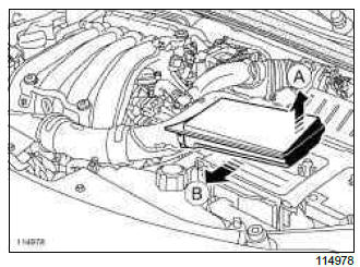
- Remove the air resonator on the battery following the direction of the arrows (A) then (B).
- Remove the battery (see Battery: Removal - Refitting) (80A, Battery).
- Remove:
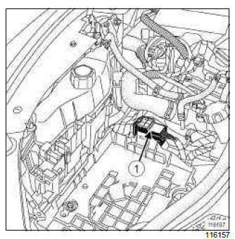
- the modular connector (1),
- the air filter (see Air filter: Removal - Refitting) (12A, Fuel mixture),
- the battery tray (see ) (80A, Battery).
- Drain the cooling system (see Cooling system: Draining - Refilling) (19A, Cooling).
- Remove:
- the front wheels (see Wheel: Removal - Refitting) (35A, Wheels and tyres),
- the front bumper (see Front bumper: Removal - Refitting) (55A, Exterior protection),
- the headlights (see ) (80B, Headlights) or (see Xenon headlight: Removal - Refitting) (80C, Xenon bulbs),
- the frontal impact cross member (see Front impact cross member: Removal - Refitting) (41A, Front lower structure),
- the front end panel (see Front end panel: Removal - Refitting) (42A, Upper front structure),
- the cooling radiator (see Cooling radiator: Removal - Refitting) (19A, Cooling).
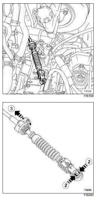
- Remove:
- the multifunction switch control (2),
- the multifunction switch sheath stop (3).
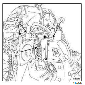
- Disconnect:
- the cooling hoses at (4) on the automatic gearbox,
- the automatic gearbox connector (5),
- the connector (6) from the automatic gearbox speed sensor,
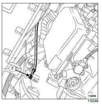
- Remove:
- the bolt (7) securing the automatic gearbox earth strap,
- the starter (see Starter: Removal - Refitting) (16A, Starting - Charging),
- the converter nuts via the starter aperture.
- Remove:
- the wiring channel mounting nuts on the body,
- the wiring channel mounting nuts on the engine.
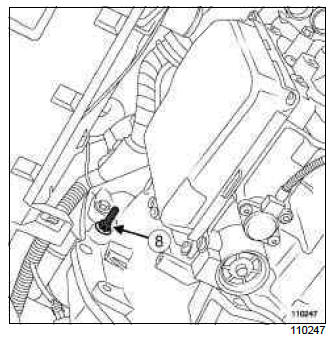
- Unscrew the nut (8) from the automatic gearbox upper stud.
- Remove:
- the left-hand driveshaft (see 29A, Driveshafts, Front left-hand driveshaft: Removal - Refitting, 29A-2),
- the right-hand driveshaft (see 29A, Driveshafts, Front right-hand driveshaft: Removal - Refitting, 29A-9).
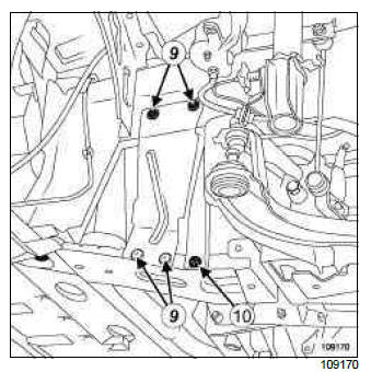
- Remove:
- the side stiffener bolts (9),
- the side stiffener,
- the tie-rod bolt (10).
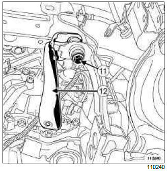
- Loosen the subframe bolt (11).
- Move the tie rod (12) back to enable access to the automatic gearbox.
- Remove the radiator support cross member (see Radiator mounting cross member: Removal - Refitting) (41A, Front lower structure).
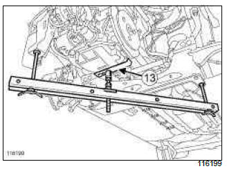
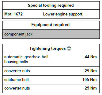
- Fit the tool (Mot. 1672) making sure that the support (13) is positioned as shown on the diagram.
- Remove:
- the left-hand suspended engine mounting (see Left-hand suspended engine mounting: Removal - Refitting) (19D, Engine mounting),
- the automatic gearbox bell housing upper bolts.
II - OPERATION FOR REMOVAL OF PART CONCERNED
- Fit the component jack beneath the automatic transmission.
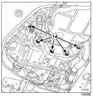
- Remove:
- the lower bolts (14) on the automatic gearbox bell housing,
- the automatic gearbox.
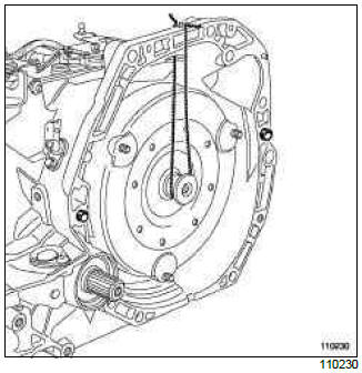
- Attach the converter with string to stop it being detached.
REFITTING
I - REFITTING PREPARATION OPERATION
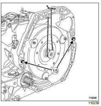
- Check that the centring dowels (15) are in place.
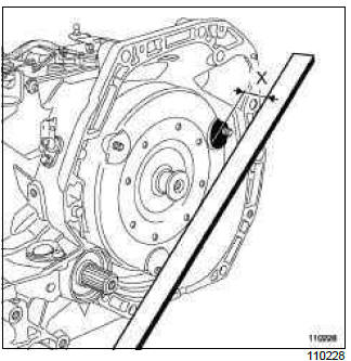
- Check the positioning of the converter in relation to the engine/automatic gearbox coupling face using a rule and a slide; the value should be at least (X) = 18.22 mm +- 1.
II - REFITTING OPERATION FOR PART CONCERNED
- Refit:
- the automatic gearbox,
- the lower bolts on the automatic gearbox bell housing,
- the converter nuts via the starter aperture.
Note: Ensure that the converter is perfectly inserted in the input shaft.
Note: Do not reuse the converter nuts or the inertia flywheel nuts if they have been removed; always fit new nuts.
III - FINAL OPERATION.
- Remove the tool component jack under the automatic gearbox.
- Refit the automatic gearbox upper bolts.
- Tighten to torque:
- the automatic gearbox bell housing bolts (44 Nm),
- the converter nuts (25 Nm).
- Refit the left-hand suspended engine mounting (see Left-hand suspended engine mounting: Removal - Refitting) (19D, Engine mounting).
- Remove the (Mot. 1672).
- Refit the radiator support cross member (see Radiator mounting cross member: Removal - Refitting) (41A, Front lower structure).
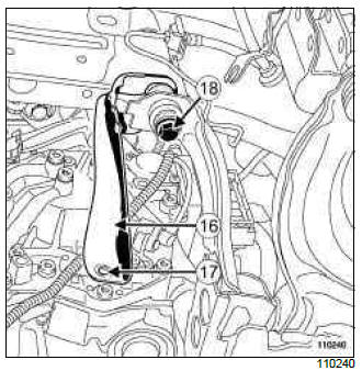
- Fit the tie-rod (16).
- Refit the tie-rod bolt at (17).
- Torque tighten the subframe bolt (105 Nm) (18).
- Refit:
- the side stiffener,
- the left-hand driveshaft (see 29A, Driveshafts, Front left-hand driveshaft: Removal - Refitting, 29A-2),
- the right-hand driveshaft (see 29A, Driveshafts, Front right-hand driveshaft: Removal - Refitting, 29A-9),
- the wiring channel mounting nuts on the body,
- the wiring channel mounting nuts on the engine.
- Torque tighten the converter nuts (25 Nm).
- Refit:
- the starter (see Starter: Removal - Refitting) (16A, Starting - Charging),
- the earth strap on the automatic gearbox,
- the automatic gearbox earth strap bolt.
- Connect:
- the automatic gearbox connector,
- the automatic gearbox speed sensor connector,
- the cooling hoses on the automatic gearbox.
- Refit:
- the multifunction switch sheath stop,
- the multifunction switch control,
- the cooling radiator (see Cooling radiator: Removal - Refitting) (19A, Cooling),
- the front end panel (see Front end panel: Removal - Refitting) (42A, Upper front structure),
- the frontal impact cross member (see Front impact cross member: Removal - Refitting) (41A, Front lower structure),
- the headlights (see ) (80B, Headlights) or (see Xenon headlight: Removal - Refitting) (80C, Xenon bulbs),
- the front bumper (see Front bumper: Removal - Refitting) (55A, Exterior protection),
- the front wheels (see Wheel: Removal - Refitting) (35A, Wheels and tyres),
- the battery tray (see ) (80A, Battery),
- the air filter (see Air filter: Removal - Refitting) (12A, Fuel mixture),
- the modular connector,
- the battery (see Battery: Removal - Refitting) (80A, Battery).
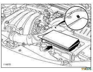
- Push the air resonator towards the rear of the vehicle so that the corner of the air resonator is between the two lines marked on the air inlet hose.
- Press on the air resonator to fit it onto the battery cover.
- Perform the following operations:
- fill the cooling system (see Cooling system: Draining - Refilling) (19A, Cooling),
- bleed the cooling system (see ) (19A, Cooling).
- Refit:
- the engine cover,
- the engine undertray.

