Renault Clio: Brake servo: Check
RIGHT-HAND DRIVE
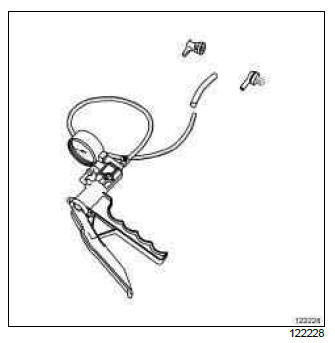
There is no "RENAULT" tool to check the braking assistance circuit.
Use a vacuum pump fitted with couplings, part numbers 7701349942 and 7700105874 with hose part number 8200027352 or 8200376245.
CHECK
I - CHECKING THE SEALS
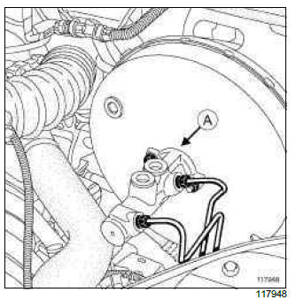
- When checking the brake servo seal, ensure that there is a perfect seal
between this and the master cylinder (A).
If there is a leak in this area, replace the seal between the brake servo and the master cylinder (see 37A, Mechanical component controls, Master cylinder: Removal - Refitting, 37A-2).
The brake servo seals must be checked on the vehicle with the hydraulic circuit operational.
II - CHECKING THE BRAKE SERVO
- Remove the front engine cover (if fitted to the vehicle).
D4F, and 784
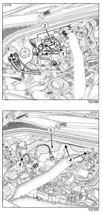
- Remove:
- the bolts (1) from the turbocharger heat shield,
- the turbocharger heat shield (2),
- the oxygen sensor (3) (see Oxygen sensors: Removal - Refitting) (MR 392, 17B, Petrol injection),
- the bulkhead heat shield clips (4),
- the bulkhead heat shield (5).
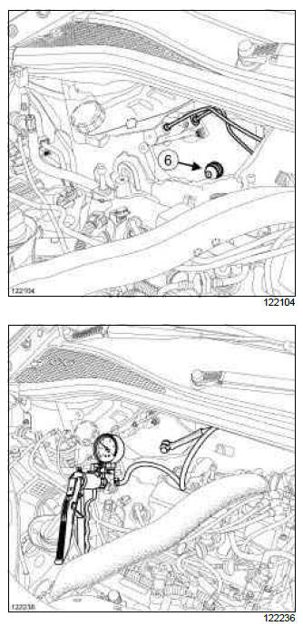
- Remove the non-return valve (6) of the brake servo (see 37A, Mechanical component controls, Brake servo non-return valve: Removal - Refitting, 37A-26).
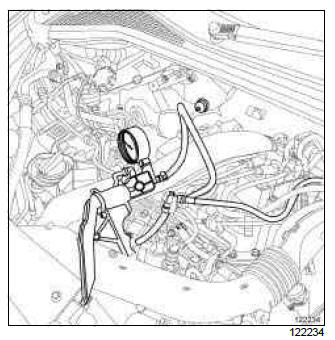
- Connect a vacuum pump directly to the brake servo.
- Activate the vacuum pump to obtain a vacuum of 500 mbar.
- Check that the vacuum does not fall by more than 33
mbar in 15 seconds.
If the vacuum falls by more than 33 mbar in 15 seconds, there is a leak which may be located:
- in the non-return valve seal, in which case replace the seal (see 37A, Mechanical component controls, Brake servo non-return valve: Removal - Refitting, 37A-26),
- in the pushrod diaphragm, in which case replace the brake servo (see 37A, Mechanical component controls, Brake servo: Removal - Refitting, 37A-32).
- Refit the non-return valve on the brake servo (see 37A, Mechanical component controls, Brake servo non-return valve: Removal - Refitting, 37A-26).
D4F, and 784
- Refit:
- the bulkhead heat shield,
- the bulkhead heat shield clips,
- the oxygen sensor (see Oxygen sensors: Removal - Refitting) (MR 392, 17B, Petrol injection),
- the turbocharger heat shield,
- the turbocharger heat shield bolts.
III - CHECKING THE NON-RETURN VALVE
D4F or F4R or K4J or K4M or M4R
- Disconnect the non-return valve on the inlet manifold side.
K9K
- Disconnect the non-return valve on the vacuum pump side.
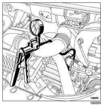
- Connect a vacuum pump to the end of the non-return valve.
- Activate the vacuum pump to obtain a vacuum of 500 mbar.
- Check that the vacuum pressure does not drop. If it does, the non-return valve is pierced. Replace the valve (see 37A, Mechanical component controls, Brake servo non-return valve: Removal - Refitting, 37A-26).
D4F or F4R or K4J or K4M or M4R
- Refit the non-return valve on the inlet manifold.
- Refit the front engine cover (if fitted to the vehicle).
IV - CHECKING THE VACUUM PUMP
K9K
- Connect the external vacuum pump to the engine vacuum pump.
- Start the engine.
- Check the following values:
- 550 mbar in 5 seconds at an engine speed of 700 rpm,
- 700 mbar in 3 seconds and 900 mbar in 5 seconds at an engine speed of 4050 rpm.
- Replace the vacuum pump if the values are different (see 37A, Mechanical component controls, Vacuum pump: Removal - Refitting, 37A-68).
- Refit the non-return valve to the vacuum pump.
READ NEXT:
 Hydraulic unit without ESP: Removal - Refitting
LEFT-HAND DRIVE
WARNING
Prepare for the flow of fluid, and protect the surrounding
components.
REMOVAL
I - REMOVAL PREPARATION OPERATION
Position the vehicle on a two-post lift (see Vehicle:
Towin
Hydraulic unit with ESP: Removal - Refitting
LEFT-HAND DRIVE
WARNING
Prepare for brake fluid outflow, to prevent damage
to the mechanical parts and bodywork around the
braking system.
REMOVAL
I - REMOVAL PREPARATION OPERATION
Position the veh
SEE MORE:
Driving
The Renault Clio IV (2014-2019) offers a satisfying driving experience with its nimble handling and responsive performance. Its compact size and maneuverability make it well-suited for urban driving and tight parking spaces. The precise steering and suspension tuning provide a balanced and confident
Your comfort
The Renault Clio IV (2014-2019) is designed with your comfort in mind. It features a well-crafted interior with quality materials and thoughtful ergonomics. The seats offer excellent support and adjustability, providing a comfortable driving experience. The cabin is designed to minimize noise and vi
