Renault Clio: Hydraulic unit with ESP: Removal - Refitting
LEFT-HAND DRIVE
WARNING
Prepare for brake fluid outflow, to prevent damage to the mechanical parts and bodywork around the braking system.
REMOVAL
I - REMOVAL PREPARATION OPERATION
- Position the vehicle on a two-post lift (see Vehicle: Towing and lifting) (MR 392, 02A, Lifting equipment).
- Disconnect the battery (see Battery: Removal - Refitting) (MR 392, 80A, Battery).
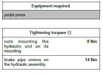
- Fit the pedal press to the brake pedal to limit the outflow of brake fluid.
F4R or K9K
- Remove:
- the wiper arms (see Wiping arm: Removal - Refitting) (MR 392, 85A, Wiping - Washing),
- the scuttle panel grille (see Scuttle panel grille: Removal - Refitting) (MR 392, 56A, Exterior equipment),
- the scoop under the scuttle panel grille (see Scuttle panel grille: Removal - Refitting) (MR 392, 56A, Exterior equipment).
M4R
- Remove the intake distributor (see Inlet distributor: Removal - Refitting) (MR 392, 12A, Fuel mixture).
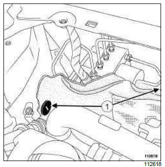
- Remove the two soundproofing clips (1).
- Move the soundproofing aside to access the hydraulic unit.
K4J or K4M
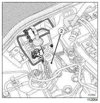
- Remove the lifting eye (2).
II - OPERATION FOR REMOVAL OF PART CONCERNED
D4F or K4J or K4M or M4R
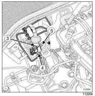
- Disconnect the hydraulic unit computer connector (3) by lifting the lug (4).
- Remove the brake pipe unions on the hydraulic unit.
- Loosen the nuts (5) mounting the hydraulic unit on its mounting.
F4R or K9K
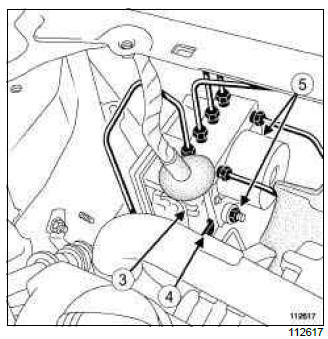
- Disconnect the hydraulic unit computer connector (3) by lifting the lug (4).
- Remove the brake pipe unions on the hydraulic unit.
- Loosen the nuts (5) mounting the hydraulic unit on its mounting.
- Remove the hydraulic unit.
REFITTING
I - REFITTING OPERATION FOR PART CONCERNED
- Refit the hydraulic unit.
- Torque tighten the nuts mounting the hydraulic unit on its mounting (8 Nm).
- Refit the six brake pipe unions on the hydraulic unit.
- Torque tighten the brake pipe unions on the hydraulic assembly (14 Nm).
- Connect the hydraulic unit computer connector.
II - FINAL OPERATION.
K4J or K4M
- Refit the lifting eye.
F4R or K9K
- Refit:
- the scoop under the scuttle panel grille (see Scuttle panel grille: Removal - Refitting) (MR 392, 56A, Exterior equipment),
- the scuttle panel grille (see Scuttle panel grille: Removal - Refitting) (MR 392, 56A, Exterior equipment),
- the wiper arms (see Wiping arm: Removal - Refitting) (MR 392, 85A, Wiping - Washing).
- Remove the pedal press tool on the brake pedal.
- Bleed the brake circuit (see 30A, General information, Braking circuit: Bleed, 30A-4).
- Connect the battery (see Battery: Removal - Refitting) (MR 392, 80A, Battery).
RIGHT-HAND DRIVE
WARNING
Prepare for the flow of fluid, and protect the surrounding components.
REMOVAL
I - REMOVAL PREPARATION OPERATION
- Position the vehicle on a two-post lift (see Vehicle: Towing and lifting) (MR 392, 02A, Lifting equipment).
- Disconnect the battery (see Battery: Removal - Refitting) (MR 392, 80A, Battery).
- Position a pedal press on the brake pedal to limit the outflow of brake fluid.
- Remove:
- the battery (see Battery: Removal - Refitting) (MR 392, 80A, Battery),
- the battery tray (see Battery tray: Removal - Refitting) (MR 392, 80A, Battery),
- the air filter unit (see Air filter unit: Removal - Refitting) (MR 392, 12A, Fuel mixture).
II - OPERATION FOR REMOVAL OF PART CONCERNED
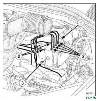
- Lift the lock at the bottom of the hydraulic unit computer connector (1).
- Disconnect the computer connector from the hydraulic unit.
- Remove:
- the brake pipe unions (2) on the hydraulic unit,
- the nuts (3) on the hydraulic unit support,
- the hydraulic unit.
REFITTING
I - REFITTING OPERATION FOR PART CONCERNED
- Refit:
- the hydraulic unit,
- the nuts on the hydraulic unit support.
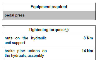
- Torque tighten the nuts on the hydraulic unit support (8 Nm).
- Finger tighten the brake pipe unions on the hydraulic unit.
- Torque tighten the brake pipe unions on the hydraulic assembly (14 Nm).
- Connect the computer connector on the hydraulic unit.
- Lower the hydraulic unit computer connector lock.
II - FINAL OPERATION.
- Refit:
- the air filter unit (see Air filter unit: Removal - Refitting) (MR 392, 12A, Fuel mixture),
- the battery tray (see Battery tray: Removal - Refitting) (MR 392, 80A, Battery),
- the battery (see Battery: Removal - Refitting) (MR 392, 80A, Battery).
- Remove the pedal press from the brake pedal.
- Connect the battery (see Battery: Removal - Refitting) (MR 392, 80A, Battery).
- Bleed the brake circuit (see 30A, General information, Braking circuit: Bleed, 30A-4).
READ NEXT:
 Wheel speed sensor: Removal - Refitting
EQUIPMENT LEVEL EAC or EQUIPMENT LEVEL SPORT
REMOVAL
I - REMOVAL PREPARATION OPERATION
Position the vehicle on a two-post lift (see 02A, Lifting
Equipment, Vehicle: Towing and lifting).
Disconnec
 Lateral acceleration and yaw sensor: Removal - Refitting
REMOVAL
I - REMOVAL PREPARATION OPERATION
Disconnect the battery (see Battery: Removal - Refitting)
(MR 392, 80A, Battery).
Remove the centre console (see Centre console:
Removal - Refitting) (M
 Braking computer: Removal - Refitting
Note:
Removal of the ESP or ABS computer is allowed.
REMOVAL
I - REMOVAL PREPARATION OPERATION
Position the vehicle on a two-post lift (see Vehicle:
Towing and lifting) (MR 392, 02A, Lifting equip
SEE MORE:
 Underbody heights: Adjustment value
I - MEASURING POINTS
Radius under load:
(R1) : Distance between the ground and the front
wheel shaft
(R2) : Distance between the ground and the rear
wheel shaft
1 - Front height (W1)
(W1) : Height between the ground and the rear cross
member bolt head
2 - Rear height (W2)
(W2) : Height be
 Fuel temperature sensor: Removal - Refitting
K9K, and 750 or 752 or 766 or 768
IMPORTANT
Use the diagnostic tool before any operation is carried
out on the injection circuit to check:
that the injector rail is not under pressure,
that the fuel temperature is not too high.
It is essential to respect the safety and cleanliness
advice whenev
© 2016-2026 Copyright Renault Clio Owners Club

