Renault Clio: D4F, and Left-hand Drive
Renault Clio III (2005-2013) Service Manual / Chassis / Mechanical Component Controls / Brake servo: Removal - Refitting / D4F, and Left-hand Drive
REMOVAL
I - REMOVAL PREPARATION OPERATION
- Put the vehicle on a two-post lift (see Vehicle: Towing and lifting).
- Disconnect the battery (see Battery: Removal - Refitting).
- Remove:
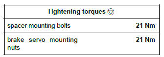
- the non-return valve (1) from the servo,
- the master cylinder (see 37A, Mechanical component controls, Master cylinder: Removal - Refitting, 37A-2),
- the lower cover strip,
- the side section of the lower cover.
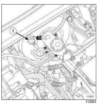
- Remove:
- the bolts (2),
- the clip (3).
- the lower cover (4), disconnecting the various connectors.
II - OPERATION FOR REMOVAL OF PART CONCERNED
- Remove:
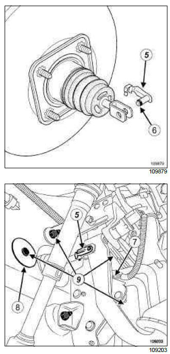
- the double safety connecting shaft (5) from between the brake servo pushrod and the brake pedal and, after tilting the connecting shaft upwards, move ring (6) using a flat-blade screwdriver.
- the accelerator pedal connector (7),
- the accelerator pedal connector wiring harness clip,
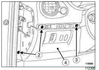
- the brake servo mounting nut blanking cover (8),
- the brake servo mounting nuts (9),
- the brake servo.
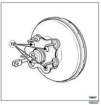
- Remove:
- the brake servo spacer mounting bolts (10),
- the brake servo spacer.
REFITTING
I - REFITTING PREPARATION OPERATION
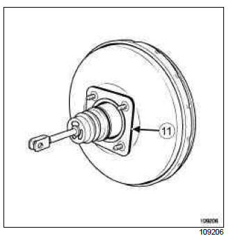
- Check that the brake servo seal (11) is present; replace the seal if it is faulty.
- The shaft connecting the brake servo pushrod and the brake pedal must be replaced every time it is removed.
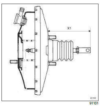
- Check the following dimension before refitting: (X1) = 174 mm.
II - REFITTING OPERATION FOR PART CONCERNED
- Refit:
- the brake servo spacer.
- the brake servo spacer mounting bolts,
- Tighten to torque the spacer mounting bolts (21 Nm).
- Refit:
- the brake servo,
- the brake servo mounting nuts,
- The shaft connecting the brake servo pushrod and the brake pedal must be put back from right to left, and from top to bottom.
- Tighten to torque the brake servo mounting nuts (21 Nm).
- Refit:
- the brake servo mounting nut blanking cover,
- the accelerator pedal connector wiring harness clip,
- the accelerator pedal connector.
III - FINAL OPERATION
- Refit:
- the lower cover, connecting the various connectors.
- the clip,
- the bolts,
- the side section of the lower cover.
- the lower cover strip,
- Refit:
- the master cylinder (see 37A, Mechanical component controls, Master cylinder: Removal - Refitting, 37A-2),
- the non-return valve on the servo,
- Bleed the brake circuit (see 30A, General information, Braking circuit: Bleed, 30A-4).
IMPORTANT
Check that the connecting shaft between the brake servo pushrod and the brake pedal is locked in place.
- Adjust the brake circuit (see 37A, Mechanical component controls, Brake pedal switch: Removal - Refitting, 37A-79).
READ NEXT:
 K4J or K4M, and Right-hand Drive
REMOVAL
I - REMOVAL PREPARATION OPERATION
Position the vehicle on a two-post lift (see Vehicle:
Towing and lifting) (MR 392, 02A, Lifting equipment).
Disconnect the battery (see Battery: Removal
D4F, and Right-hand Drive
REMOVAL
I - REMOVAL PREPARATION OPERATION
Position the vehicle on a two-post lift (see Vehicle:
Towing and lifting) (MR 392, 02A, Lifting equipment).
Disconnect the battery (see Battery: Removal
F4R, and Left-hand Drive
REMOVAL
I - REMOVAL PREPARATION OPERATION
Position the vehicle on a two-post lift (see Vehicle:
Towing and lifting) (MR 392, 02A, Lifting equipment).
Remove:
the battery (see Battery: Remova
SEE MORE:
Maintenance
The maintenance of the Renault Clio IV (2014-2019) involves following the recommended guidelines provided in the owner's manual. Regular maintenance tasks include oil changes, filter replacements, and inspections of important components such as brakes, tires, and fluids. Adhering to the maintenance
Bonnet
To open the bonnet, pull the handle 1.
Before performing any
action in the engine compartment,
the ignition must
be switched off by pressing
the engine stop button (please see
the information on “Starting, stopping
the engine” in Section 2).
Unlocking the bonnet c
© 2016-2026 Copyright Renault Clio Owners Club - 0.0037
