Renault Clio: D4F, and 740 or 742 or 764

REMOVAL
I - REMOVAL PREPARATION OPERATION
- Position the vehicle on a two-post lift (see Vehicle: Towing and lifting).
IMPORTANT
During this operation, secure the vehicle to the lift with a strap to prevent it from becoming unbalanced.
For strapping the vehicle (see 02A, Lifting equipment, Vehicle: Towing and lifting).
- Remove:
- the air filter box (see 12A, Fuel mixture, Air filter unit: Removal - Refitting, 12A-17),
- the battery (see Battery: Removal - Refitting),
- the battery tray,
- the engine undertray.
- Drain:
- the cooling system (see 19A, Cooling, Cooling system: Draining - Refilling, 19A-16),
- the gearbox (see Manual gearbox oils: Draining - Filling),
- the engine if necessary (see 10A, Engine and cylinder block assembly, Engine oil: Draining - Refilling, 10A-12).
AIR CONDITIONING
- Drain the coolant circuit (see Air conditioning: Parts and consumables for the repair).
- Remove:
- the front wheels (see Wheel: Removal - Refitting),
- the front wheel arch liners (see MR 393 Bodywork, 55A, Exterior protection, Front wheel arch liners),
- the front bumper (see MR 393, Bodywork, 55A, Exterior protection, Front bumper: Removal - Refitting),
- the " left-hand driveshaft-stub axle carrier " assembly, (see Hub carrier - driveshaft assembly: Removal - Refitting)
- the " right-hand driveshaft-stub axle carrier " assembly.
(see Hub carrier - driveshaft assembly: Removal - Refitting)
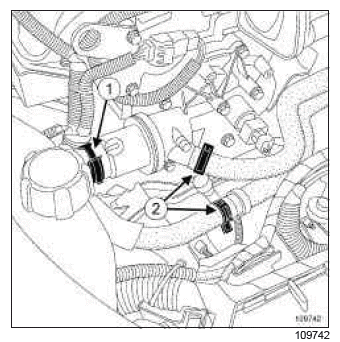
- Disconnect:
- the engine cooling fan assembly connectors,
- the top hose (1) on the cylinder head coolant pipe housing outlet,
- the passenger compartment heater hoses (2).
- Remove the expansion bottle (see 19A, Cooling, Expansion bottle: Removal - Refitting, 19A- 101).
AIR CONDITIONING
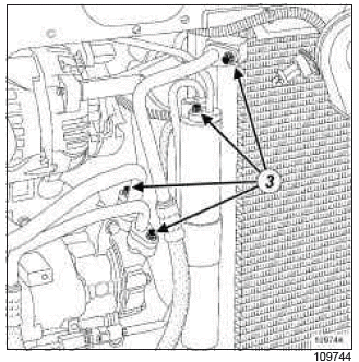
- Unclip the wiring harness of the pressure switch on the condenser.
- Disconnect:
- the pressure switch from the condenser,
- the air conditioning compressor clutch connector.
- Remove the air conditioning pipe union mounting bolts (3) on the compressor, evaporator and condenser.
- Fit plugs into the openings.
- Remove:
- the radiator mounting cross member (see MR 393 Bodywork, 41A, Lower front structure, Radiator mounting cross member: Removal - Refitting).
- the cooling radiator (see 19A, Cooling, Cooling radiator: Removal - Refitting, 19A-20),
- the earths,
- the Protection and Switching Unit cover.
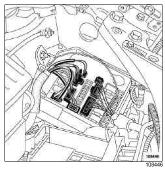
- Disconnect the connectors from the protection and switching unit.
- Unclip the oxygen sensor harnesses.
- Disconnect:
- the brake servo pipe,
- the oxygen sensor connectors,
- the petrol vapour rebreather connector,
- the connector from the lifting eye at the flywheel end,
- Disconnect:
- the fuse,
- the fuse holder to the fuse board,
- the supply cable on the fuse board,
- the supply cable from the battery protection fuse box.
- Remove:
- the petrol injection computer (see 17B, Petrol injection, Petrol injection computer: Removal - Refitting, 17B-37),
- the computer support mounting bolts,
- the computer bracket.
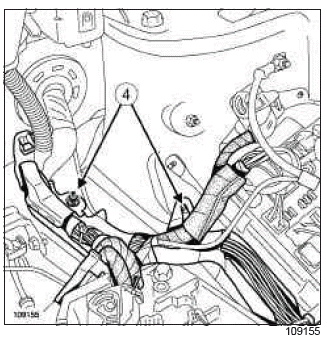
- Remove the wiring channel mounting bolts (4) on the body.
- Remove the wiring duct.
- Disconnect:
- the canister solenoid valve connector,
- the canister solenoid valve pipe,
- the petrol supply pipe from the injector rail.
- Fit plugs into the openings.
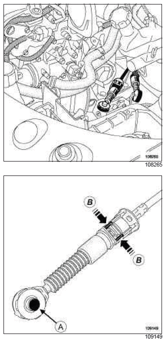
- Remove:
- the gear control cables on the gearbox by pushing at (A),
- the control cables by pushing at (B),
- the wiring harness channel mountings on the gearbox.
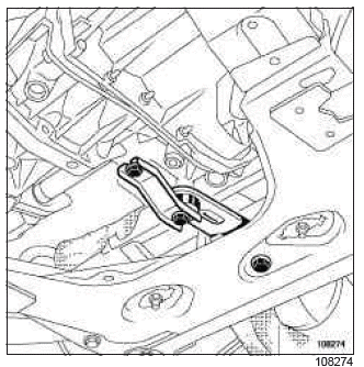
- Remove:
- the engine tie-bar (see 19D, Engine mounting, Lower engine tie-bar: Removal - Refitting, 19D-13),
- the exhaust downpipe mountings.
- Fit a hose clamp between the brake fluid reservoir and the clutch master cylinder.
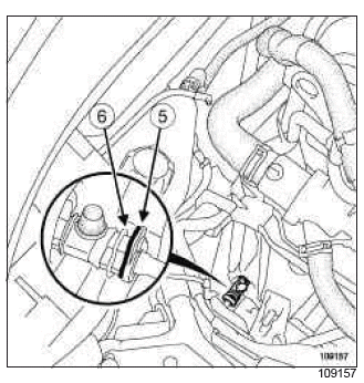
- Disconnect the clutch slave cylinder by pulling the clips (5) and (6)
- Collect the fluid in a container.
WARNING
Fit plugs into the openings.
Plugs must be fitted on the pipes to prevent moisture from entering the system.
- Unclip the gearbox clutch pipe.
II - OPERATION FOR REMOVAL OF PART CONCERNED
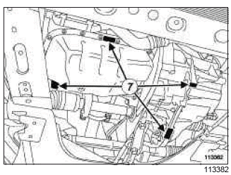
- Support the " engine - gearbox " assembly on the engine marks (7) with the (Mot. 1390).
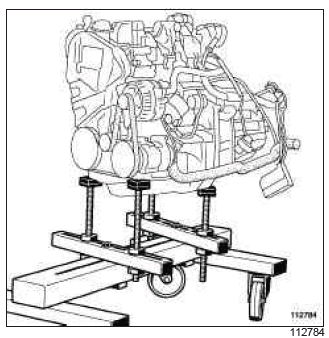
- Mark the positions of the suspended engine mountings on the body.
- Remove:
- the right-hand suspended engine mounting (see 19D, Engine mounting, Right-hand suspended engine mounting: Removal - Refitting, 19D-22),
- the left-hand suspended engine mounting (see 19D, Engine mounting, Left-hand suspended engine mounting: Removal - Refitting, 19D-34).
- Raise the vehicle, moving the engine towards the front.
- Remove the " engine - gearbox " assembly.
REFITTING
I - REFITTING PREPARATION OPERATION
- If carrying out a standard engine replacement (see Technical Note 6004A, 4 cylinder - D4 - petrol engine, 10A, Engine and peripherals, Standard replacement).
II - REFITTING OPERATION FOR PART CONCERNED
- Position the " engine - gearbox " assembly in the vehicle.
- Refit:
- the left-hand suspended engine mounting (see 19D, Engine mounting, Left-hand suspended engine mounting: Removal - Refitting, 19D-34),
- the right-hand suspended engine mounting (see 19D, Engine mounting, Right-hand suspended engine mounting: Removal - Refitting, 19D-22).
- Remove the (Mot. 1390) from the " engine - gearbox " assembly.
III - FINAL OPERATION.
- Clip the clutch pipe to the gearbox.
- Remove the protective plugs from the pipe openings.
- Connect the clutch slave cylinder pipes.
- Remove the hose clamp between the brake fluid reservoir and the clutch master cylinder.
- Refit the exhaust downpipe mountings.
- Torque tighten the exhaust downpipe mountings (9 N.m).
- Refit the engine tie-bar (see 19D, Engine mounting, Lower engine tie-bar: Removal - Refitting, 19D-13).
- Refit the wiring harness channel mountings on the gearbox.
- Refit the gearbox control cables.
- Remove the protective plug from the injector rail.
- Connect:
- the fuel supply pipe to the injector rail,
- the canister solenoid valve pipe,
- the canister solenoid valve connector.
- Refit the wiring harness channel mountings to the body.
- Refit:
- the wiring harness channel mountings to the body,
- the computer mounting,
- the computer bracket mounting bolts bolts,
- the injection computer (see 17B, Petrol injection, Petrol injection computer: Removal - Refitting, 17B-37).
- Connect:
- the supply cable on the battery protection fuse box,
- the supply cable on the fuse board,
- the fuse holder to the fuse board,
- the fuse,
- the connector on the lifting eye at the flywheel end,
- the petrol vapour rebreather connector,
- the oxygen sensor connectors,
- the brake servo pipe,
- the Protection and Switching Unit connectors.
- Refit:
- the Protection and Switching Unit cover,
- the earths,
- the cooling radiator (see 19A, Cooling, Cooling radiator: Removal - Refitting, 19A-20),
- the radiator mounting cross member (see MR 393 Bodywork, 41A, Lower front structure, Radiator mounting cross member: Removal - Refitting).
- Clip the oxygen sensor wiring harnesses into place.
AIR CONDITIONING
- Refit the air conditioning pipe mounting bolts on the compressor, evaporator and condenser.
- Torque tighten the air conditioning mounting bolts on the compressor, evaporator and condenser (8 N.m).
- Connect:
- the pressure switch from the condenser,
- the air conditioning compressor clutch connector.
- Clip the pressure switch wiring harness on the condenser.
- Refit the expansion bottle (see 19A, Cooling, Expansion bottle: Removal - Refitting, 19A- 101).
- Connect:
- the passenger compartment heating hoses,
- the top hose from the cylinder head coolant outlet unit,
- the fan assembly connectors.
- Refit:
- the " right-hand driveshaft and stub-axle carrier assembly " (see Hub carrier - driveshaft assembly: Removal - Refitting),
- the " left-hand driveshaft and stub axle carrier assembly " (see Hub carrier - driveshaft assembly: Removal - Refitting),
- the front bumper (see MR 393, Bodywork, 55A, Exterior protection, Front bumper: Removal - Refitting),
- the front wheel arch liners (see MR 393 Bodywork, 55A, Exterior protection, Front wheel arch liners),
- the front wheels (see Wheel: Removal - Refitting).
- Refill:
- the engine if necessary (see 10A, Engine and cylinder block assembly, Engine oil: Draining - Refilling, 10A-12),
- the gearbox (see Manual gearbox oils: Draining - Filling),
- the engine cooling circuit (see 19A, Cooling, Cooling system: Draining - Refilling, 19A-16).
- Refit:
- the engine undertray,
- the battery tray,
- the battery (see Battery: Removal - Refitting),
- the air filter box (see 12A, Fuel mixture, Air filter unit: Removal - Refitting, 12A-17).
AIR CONDITIONING
- Refill the coolant circuit (see Air conditioning: Parts and consumables for the repair).
READ NEXT:
 M4R, and DP0
REMOVAL
I - REMOVAL PREPARATION OPERATION
Position the vehicle on a two-post lift (see Vehicle:
Towing and lifting) (MR 392, 02A, Lifting equipment).
IMPORTANT
During this operation, secure the
 F4R
F4R
REMOVAL
I - REMOVAL PREPARATION OPERATION
Position the vehicle on a two-post lift (see Vehicle:
Towing and lifting) (MR 392, 02A, Lifting equipment).
IMPORTANT
During this operation, secure the
 M4R, and TL4
REMOVAL
I - REMOVAL PREPARATION OPERATION
Position the vehicle on a two-post lift (see Vehicle:
Towing and lifting) (02A, Lifting equipment).
Remove the front engine cover.
Disconnect the batte
SEE MORE:
 Rear Seat Frames And Mechanisms
Single unit rear bench seatback: Removal - Refitting
REMOVAL
I - REMOVAL PREPARATION OPERATION
Remove the single unit rear bench seat base (see
76A, Rear seat frames and mechanisms, Single
unit rear bench seat base: Removal - Refitting, 76A-6).
II - OPERATION FOR REMOVAL OF PART
CONCERNED
R
 Cabin filter: Removal - Refitting
LEFT-HAND DRIVE
Note:
The cabin filter is located in the passenger side A-pillar.
REMOVAL
I - REMOVAL PREPARATION OPERATION
SCHOOL VEHICLE
Remove the clutch pedal (see Clutch pedal: Removal
- Refitting) (MR392, 37A, Mechanical component
controls).
II - OPERATION FOR REMOVAL OF PART
CONCERNED
© 2016-2026 Copyright Renault Clio Owners Club

