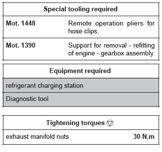
Renault Clio: F4R
REMOVAL
I - REMOVAL PREPARATION OPERATION
- Position the vehicle on a two-post lift (see Vehicle: Towing and lifting) (MR 392, 02A, Lifting equipment).
IMPORTANT
During this operation, secure the vehicle to the lift with a strap to prevent it from becoming unbalanced.
- Disconnect the battery (see Battery: Removal - Refitting) (MR 392, 80A, Battery).
- Remove the engine undertray.
- Perform the following operations:
- drain the air conditioning circuit using the refrigerant charging station (see Refrigerant circuit: Draining - Filling) (MR 392, 62A, Air conditioning),
- drain the cooling system (see 19A, Cooling, Cooling system: Draining - Refilling, 19A-16),
- drain the gearbox oil (see Manual gearbox oils: Draining - Filling) (MR 392, 21A, Manual gearbox),
- drain the engine oil (see 10A, Engine and cylinder block assembly, Engine oil: Draining - Refilling, 10A-12).
- Remove:
- the front bumper (see Front bumper: Removal - Refitting) (MR 393, 55A, Exterior protection),
- the front end panel (see Front end panel: Removal - Refitting) (MR 393, 42A, Upper front structure),
- the battery (see Battery: Removal - Refitting) (MR 392, 80A, Battery),
- the air filter unit (see 12A, Fuel mixture, Air filter unit: Removal - Refitting, 12A-17),
- the soundproofing unit,
- the battery tray mounting (see Battery tray: Removal - Refitting) (MR 392, 80A, Battery tray).
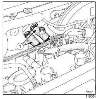
- Disconnect the hoses (1) from the heater radiator using the (Mot. 1448).
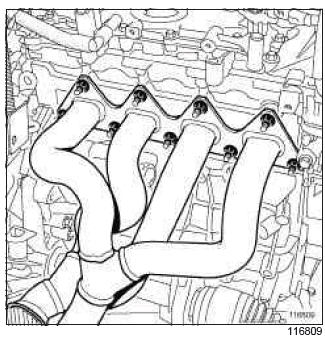
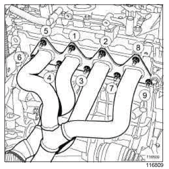
- Remove the exhaust manifold nuts.
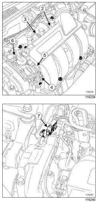
- Disconnect:
- the brake servo pipe (2) on the inlet distributor side,
- the petrol vapour rebreather pipe (3) on the inlet distributor side,
- the fuel supply pipe (4) from the injector rail,
- the connector (5) from the inlet air pressure sensor,
- the camshaft dephaser solenoid valve connector (6),
- the petrol vapour recirculation solenoid valve connector (7).
- Move the wiring harness to one side.
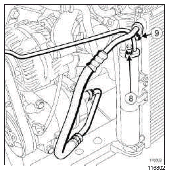
- Remove:
- the bolt (8 ) from the " expansion valve - condenser " connecting pipe,
- the " compressor - condenser " connecting pipe bolt (9).
- Disconnect:
- the " expansion valve - condenser " connecting pipe on the condenser side,
- the " compressor - condenser " connecting pipe on the condenser side,
- the cooling radiator hose on the cooling radiator using the (Mot. 1448),
- the fan assembly connectors.
- Remove:
- the " engine cooling fan - radiator - condenser - expansion bottle " assembly,
- the radiator mounting cross member (see Radiator mounting cross member: Removal - Refitting) (MR 393, 41A, Front lower structure),
- the rear suspended engine mounting (see 19D, Engine mounting, Lower engine tie-bar: Removal - Refitting, 19D-13),
- the driveshafts (see Front left-hand driveshaft: Removal - Refitting) and (see Front right-hand driveshaft: Removal - Refitting) (MR 392, 29A, Driveshafts).
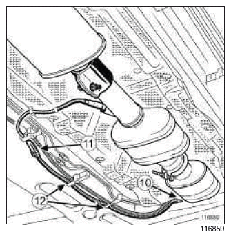
- Disconnect:
- the upstream oxygen sensor connector (10),
- the downstream oxygen sensor connector (11).
- Unclip the wiring harness at (12) from the downstream oxygen sensor.
Note: with the wiring harness sitting on the engine, it is necessary to move the heat shields aside when removing the engine.
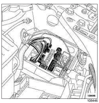
- Disconnect:
- the injection computer connectors,
- the connectors in the connection unit.
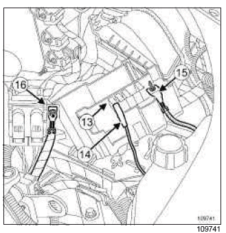
- Disconnect:
- the fuse (13),
- the fuse holder (14) from the fuse board,
- the supply cable (15) from the fuse board,
- the supply cable (16) from the battery protection fuse box.
- Remove:
- the petrol injection computer,
- the earth nut on the side member,
- the earth nut on the left-hand wheel arch.
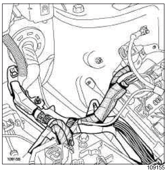
- Cut the adhesive tape in order to move the wiring harness away from its channel.
- Move the engine wiring away from the channel
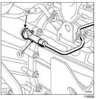
- Disconnect the clutch control duct (17) by pushing the clip (18) and moving it aside.
- Remove the gearbox controls.
II - OPERATION FOR REMOVAL OF PART CONCERNED
- Position the (Mot. 1390).
- Remove:
- the left-hand suspended engine mounting (see 19D, Engine mounting, Left-hand suspended engine mounting: Removal - Refitting, 19D-34),
- the right-hand suspended engine mounting (see 19D, Engine mounting, Right-hand suspended engine mounting: Removal - Refitting, 19D-22).
- Move the " engine-gearbox " assembly forward positioned on the (Mot. 1390).
- Raise the vehicle using a two-post lift to remove the " engine-gearbox " assembly from the engine compartment.
REFITTING
I - REFITTING PREPARATION OPERATION
- For standard engine replacements (see ) (Technical Note 6027A, 10A, Engine and peripherals).
II - REFITTING OPERATION FOR PART CONCERNED
- Position the " engine - gearbox " assembly in the engine compartment.
- Refit:
- the right-hand suspended engine mounting (see 19D, Engine mounting, Right-hand suspended engine mounting: Removal - Refitting, 19D-22),
- the left-hand suspended engine mounting (see 19D, Engine mounting, Left-hand suspended engine mounting: Removal - Refitting, 19D-34).
- Remove the tool (Mot. 1390).
III - FINAL OPERATION
- Connect the clutch control duct.
- Bleed the clutch control.
- Refit the gearbox controls.
- Fit the wiring harness.
- Refit:
- the earth nut on the left-hand wheel arch,
- the earth nut on the side member,
- the petrol injection computer.
- Connect:
- the injection computer connectors,
- the connectors in the connection unit.
- Refit the engine compartment connection unit cover.
- Position the engine wiring harness in its channel.
- Attach the wiring harness using ADHESIVE TAPE on its channel.
- Connect:
- the supply cable to the battery protection fuse box,
- the supply cable to the fuse board,
- the fuse holder to the fuse board,
- the fuse.
- Pass the downstream oxygen sensor wiring harness behind the heat shield.
- Connect:
- the upstream oxygen sensor connector,
- the downstream oxygen sensor connector.
- Clip the downstream oxygen sensor wiring harness into place.
- Refit:
- the driveshafts (see Front left-hand driveshaft: Removal - Refitting) and (see Front right-hand driveshaft: Removal - Refitting) (MR 392, 29A, Driveshafts),
- the rear suspended engine mounting (see 19D, Engine mounting, Lower engine tie-bar: Removal - Refitting, 19D-13),
- the radiator mounting cross member (see Radiator mounting cross member: Removal - Refitting) (MR 393, 41A, Front lower structure),
- the " engine cooling fan - radiator - condenser " assembly.
- Connect:
- the cooling radiator upper and lower hoses using the (Mot. 1448),
- the engine cooling fan assembly connectors,
- the cooling radiator hose to the cooling radiator using the (Mot. 1448),
- the " compressor - condenser " connecting pipe on the condenser side,
- the " expansion valve - condenser " connecting pipe on the condenser side.
- Refit:
- the bolt (9) on the " compressor - condenser " connecting pipe,
- the bolt (8) of the " expansion valve - condenser " connecting pipe.
- Connect:
- the petrol vapour recirculation solenoid valve connector.
- the camshaft dephaser solenoid valve connector,
- the inlet air pressure sensor connector,
- the fuel supply pipe on the injector rail,
- the petrol vapour rebreather pipe on the inlet distributor side,
- the brake servo pipe on the inlet distributor side
- Fit:
- a new exhaust manifold seal on the cylinder head,
- the exhaust manifold on the cylinder head.
- Refit the exhaust manifold nuts.
- Torque tighten in order the exhaust manifold nuts (30 N.m).
- Connect the heating radiator hoses using the (Mot.1448).
- Refit:
- the battery tray mounting (see Battery tray: Removal - Refitting) (MR 392, 80A, Battery tray),
- the soundproofing unit,
- the air filter unit (see 12A, Fuel mixture, Air filter unit: Removal - Refitting, 12A-17),
- the battery (see Battery: Removal - Refitting) (MR 392, 80A, Battery),
- the front end panel (see Front end panel: Removal - Refitting) (MR 393, 42A, Upper front structure),
- the front bumper (see Front bumper: Removal - Refitting) (MR 393, 55A, Exterior protection).
- Connect the battery (see Battery: Removal - Refitting) (MR 392, 80A, Battery).
- Perform the following operations:
- top up the engine oil (see 10A, Engine and cylinder block assembly, Engine oil: Draining - Refilling, 10A-12),
- fill up the gearbox oil (see Manual gearbox oils: Draining - Filling) (MR 392, 21A, Manual gearbox),
- fill the cooling system (see 19A, Cooling, Cooling system: Draining - Refilling, 19A-16),
- bleed the cooling circuit,
- fill the air conditioning circuit using the refrigerant charging station (see Refrigerant circuit: Draining - Filling) (MR 392, 62A, Air conditioning).
- Using the Diagnostic tool, check that there are no faults stored by the computer, and clear them if necessary.
- Check:
- that there are no leaks,
- using the Diagnostic tool, that there are no faults stored by the computer, and clear them if necessary.
- Refit the engine undertray.
- Carry out a road test to check that the vehicle is in good working order.
READ NEXT:
 M4R, and TL4
REMOVAL
I - REMOVAL PREPARATION OPERATION
Position the vehicle on a two-post lift (see Vehicle:
Towing and lifting) (02A, Lifting equipment).
Remove the front engine cover.
Disconnect the batte
K9K, and JA5
REMOVAL
I - REMOVAL PREPARATION OPERATION
Position the vehicle on a two-post lift (see Vehicle:
Towing and lifting) (02A, Lifting equipment).
Remove the front engine cover.
Disconnect the batte
D4F, and JA3
REMOVAL
I - REMOVAL PREPARATION OPERATION
Position the vehicle on a two-post lift (see Vehicle:
Towing and lifting) (MR 392, 02A, Lifting equipment).
Remove:
the air filter box (see 12A, Fuel m
SEE MORE:
Driving
The Renault Clio IV (2014-2019) offers a satisfying driving experience with its nimble handling and responsive performance. Its compact size and maneuverability make it well-suited for urban driving and tight parking spaces. The precise steering and suspension tuning provide a balanced and confident
Your comfort
The Renault Clio IV (2014-2019) is designed with your comfort in mind. It features a well-crafted interior with quality materials and thoughtful ergonomics. The seats offer excellent support and adjustability, providing a comfortable driving experience. The cabin is designed to minimize noise and vi
© 2016-2026 Copyright Renault Clio Owners Club - 0.0053
