Renault Clio: Dashboard wiring: Connector access
Renault Clio III (2005-2013) Service Manual / Electrical Equipment / Wiring Harness / Dashboard wiring: Connector access
I - LOCATION OF CONNECTORS
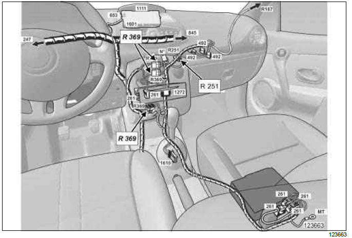
- R251 connector (dashboard wiring/radio + telephone wiring connection).
- R369 connector (dashboard wiring//multimedia wiring connection).
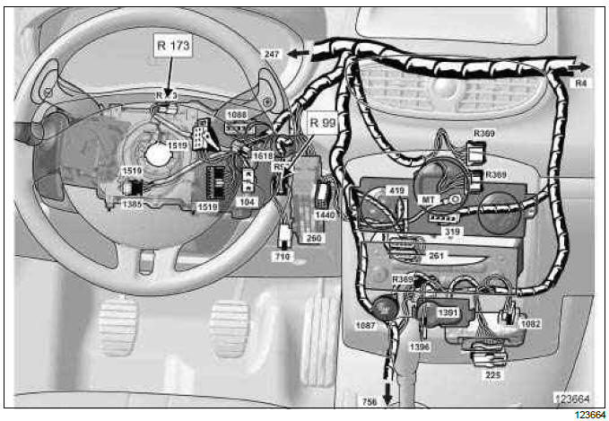
- R99 connector (dashboard wiring/heating wiring connection).
- R 173 connector (dashboard wiring/wiring for one-touch steering wheel controls on sequential gearbox).
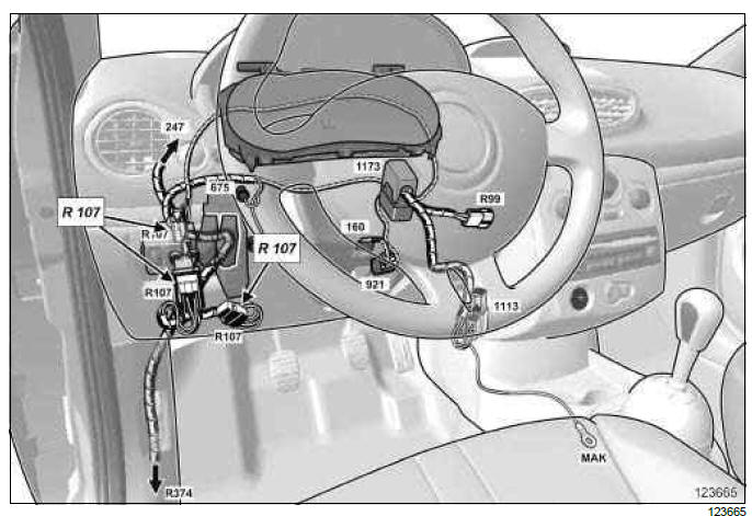
- R107 connector (dashboard wiring/front engine wiring connection).
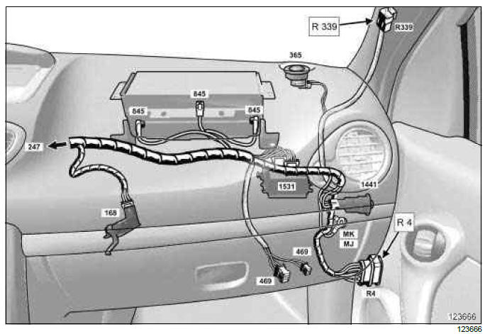
- R4 connector (dashboard wiring/passenger door wiring connection).
- R339 connector (dashboard wiring/sunroof wiring connection).
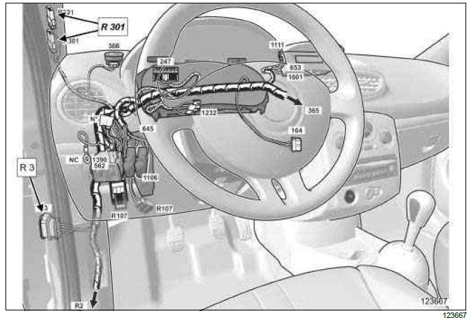
- R3 connector (dashboard wiring/driver's door wiring connection).
- R301 connector (dashboard wiring/courtesy light wiring connection).
II - ACCESS TO CONNECTORS
IMPORTANT
Consult the safety and cleanliness advice and operation recommendations before carrying out any repair (see 88A, Wiring harness, Wiring: Precautions for the repair, 88A-5).
WARNING
To prevent damaging the connectors, consult the disconnection procedure (see Connector: Disconnection and reconnection) (Technical Note 6015A, 88A, Wiring).
- Switch off the ignition.
- Disconnect the battery (see 80A, Battery, Battery: Removal - Refitting, 80A-1).
1 - Access to the R 251 connectors
- Remove:
- the radio (see 86A, Radio, Radio: Removal - Refitting, 86A-8),
- the centre front panel (see Centre front panel: Removal - Refitting) (MR 393, 57A, Interior equipment),
- the air conditioning control panel (see Control panel: Removal - Refitting) (MR 392, 61A, Heating),
2 - Access to the R 369 connectors
- Remove:
- the radio (see 86A, Radio, Radio: Removal - Refitting, 86A-8),
- the centre front panel (see Centre front panel: Removal - Refitting) (MR 393, 57A, Interior equipment),
- the air conditioning control panel (see Control panel: Removal - Refitting) (MR 392, 61A, Heating),
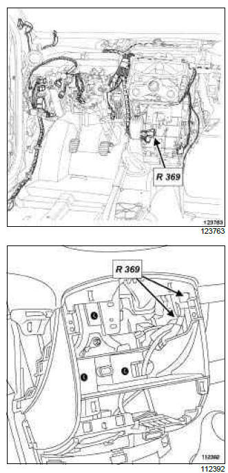
- Disconnect the R 369 connectors.
3 - Access to the R 99 connector
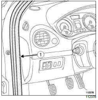
- Partially remove seal (1).
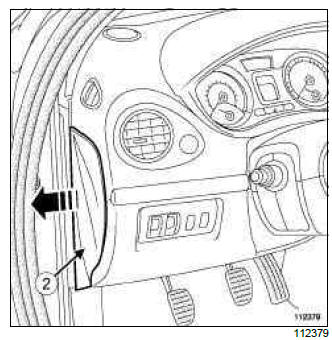
- Remove the dashboard side face (2).
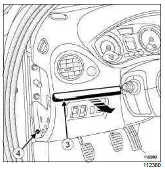
- Unclip the trim (3).
- Remove the dashboard lower trim bolt (4).
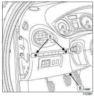
- Remove:
- the dashboard lower trim bolts (5),
- the dashboard lower trim (6).
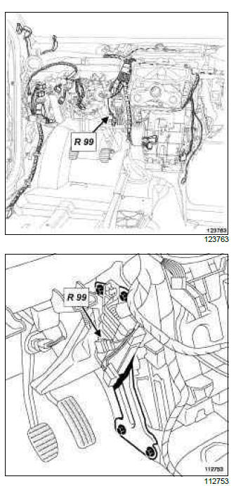
- Disconnect the R 99 connector.
4 - Access to the R 173 connector
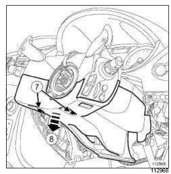
- Remove the bolts (7) from the shells under the steering wheel.
- Unclip the lower casing (8).
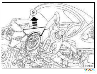
- Unclip the upper cover (9).
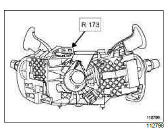
- Disconnect the R 173 connector.
5 - Access to the R 107 connectors
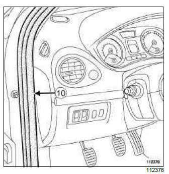
- Partially remove seal (10).
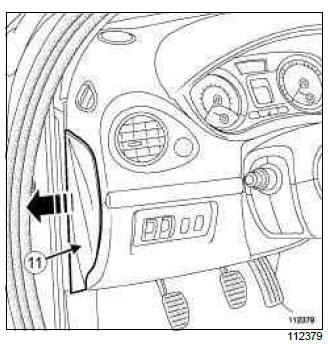
- Remove the dashboard side face (11).
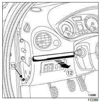
- Unclip the trim (12).
- Remove the dashboard lower trim bolt (13).
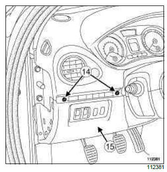
- Remove:
- the dashboard lower trim bolts (14),
- the dashboard lower trim (15).
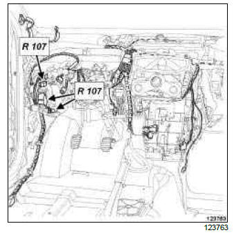
- Disconnect the R 107 connectors.
6 - Access to the R 4 connector
- Open the passenger door.
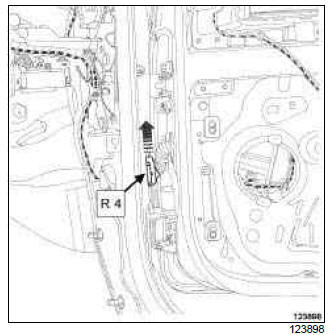
- Unclip the R 4 connector latch.
- Disconnect the R4 connector.
7 - Access to R 339 connector
- Remove the right-hand A-pillar trim (see Windscreen pillar trim: Removal - Refitting) (MR 393, 71A, Body internal trim).
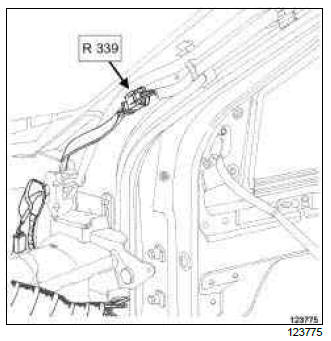
- Disconnect the R 339 connector.
8 - Access to the R 3 connector
- Open the driver's door.
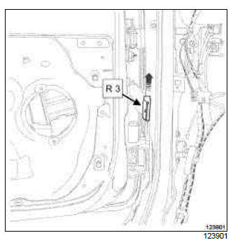
- Unclip the R 3 connector latch.
- Disconnect the R3 connector.
9 - Access to the R 301 connectors
- Remove the left-hand A-pillar trim (see Windscreen pillar trim: Removal - Refitting) (MR 393, 71A, Body internal trim).
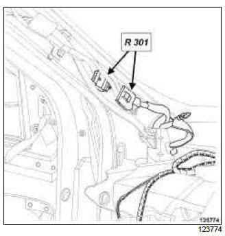
- Disconnect the R 301 connectors.
READ NEXT:
 Dashboard wiring: Removal - Refitting
LEFT-HAND DRIVE
IMPORTANT
Consult the safety and cleanliness advice and operation
recommendations before carrying out any
repair (see 88A, Wiring harness, Wiring: Precautions
for the repair, 88A-5).
Driver's front side door wiring: Removal - Refitting
IMPORTANT
Consult the safety and cleanliness advice and operation
recommendations before carrying out any
repair (see 88A, Wiring harness, Wiring: Precautions
for the repair, 88A-5).
REMOVAL
I - REMOV
Passenger's front side door wiring: Removal -
Refitting
IMPORTANT
Consult the safety and cleanliness advice and operation
recommendations before carrying out any
repair (see 88A, Wiring harness, Wiring: Precautions
for the repair, 88A-5).
REMOVAL
I - REMOV
SEE MORE:
Opening and closing the doors
Opening the doors from the outside
Front doors
With the doors unlocked, pull handle 1.
Special feature of the RENAULT
“hands-free” card
With the doors locked, press button 2
on handle 1 of one of the two front
doors and pull towards you.
Rear doors
With the doors unlocked, pull hand
Locking, unlocking the opening elements
Locking/Unlocking the doors
from the outside
This is done using the RENAULT Card;
see the “RENAULT Card” information in
Section 1.
In certain cases, the RENAULT card
may not work:
if the RENAULT card battery is weak,
flat, etc.
if equipment operating on the same
frequency as the ca
© 2016-2026 Copyright Renault Clio Owners Club - 0.0039
