Renault Clio: Engine cooling system: Operating diagram
Renault Clio III (2005-2013) Service Manual / Engine And Peripherals / Cooling / Engine cooling system: Operating diagram
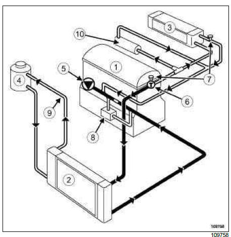
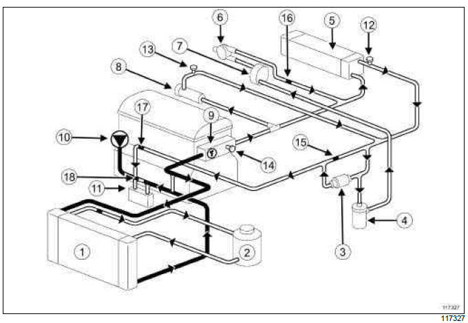
D4F
D4F, and 740 or 742 or 764
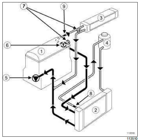
- Engine
- Cooling radiator
- heater matrix
- Expansion bottle
- Water pump
- Thermostat
- Bleed screws
- 5 mm restriction
- 10 mm restriction
Note: The rating of the expansion bottle degassing valve is 1.4 bar.
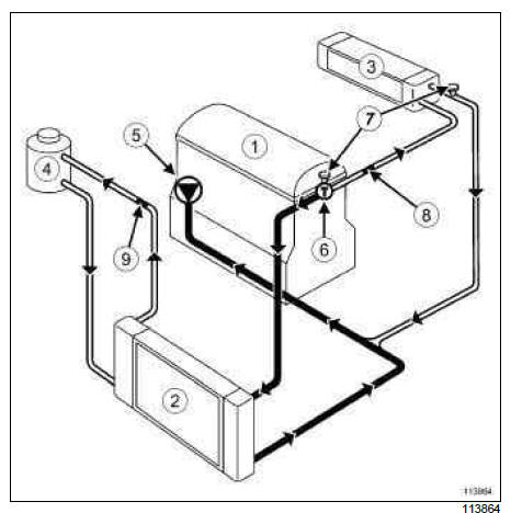
D4F, and 784
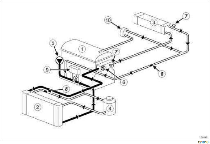
- Engine
- Cooling radiator
- Heater matrix
- Expansion bottle
- Water pump
- Thermostat
- Bleed screws
- Choke
- Coolant-oil intercooler
- Turbocharger
K4M, and 800
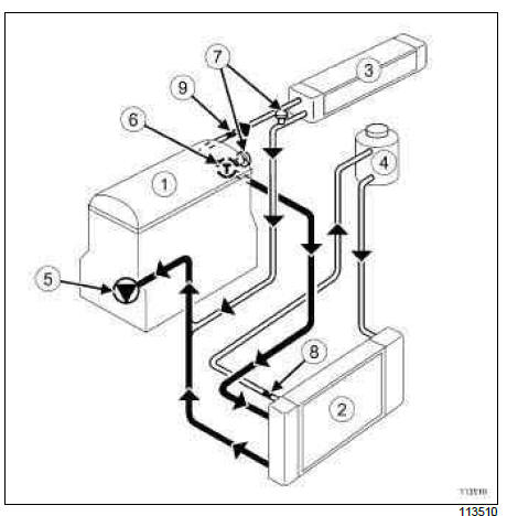
- Engine
- Cooling radiator
- Heater radiator
- Expansion bottle
- Water pump
- Thermostat
- Bleed screws
- 5 mm restriction
- 10 mm restriction
Note: The expansion bottle degassing valve rating is 1.4 bar.
K4M, and 801
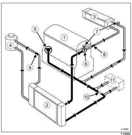
- Engine
- Cooling radiator
- Heater radiator
- Expansion bottle
- Water pump
- Thermostat
- Bleed screws
- 11 mm restriction
- 5 mm restriction
- 10 mm restriction
- Oil-water intercooler for automatic gearbox (if fitted to the vehicle)
Note: The expansion bottle degassing valve rating is 1.4 bar.
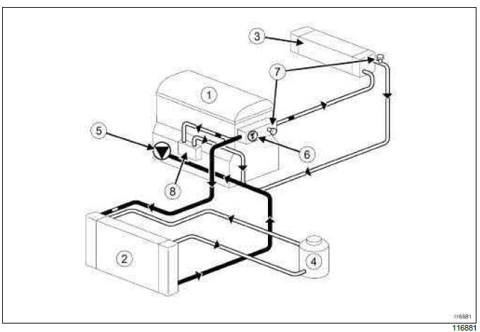
K9K, and 764 or 766 or 768
- Engine
- Cooling radiator
- Heater radiator
- Expansion bottle
- Coolant pump
- Thermostat
- Bleed screws
- Water-oil heat exchanger
- 5 mm choke
- EGR
K4J
- Engine
- Cooling radiator
- Heater radiator
- Expansion bottle
- Water pump
- Thermostat
- Bleed screws
- 11 mm restriction
- 5 mm restriction
Note: The expansion bottle degassing valve rating is 1.4 bar.
M4R
- Radiator
- Automatic transmission oil coolant heat exchanger
- Engine oil coolant heat exchanger
- Cylinder head thermostat
- Heater matrix
- Motorised throttle valve
- Cylinder block thermostat
- Expansion bottle
- Bleed screws
- 3 mm restriction
- 11 mm restriction
- 10 mm restriction
F4R
- Engine
- Cooling radiator
- Heater radiator
- Expansion bottle
- Coolant pump
- thermostat
- Bleed screw
- Engine oil cooler
Note: The rating of the expansion bottle degassing valve is 1.4 bar.
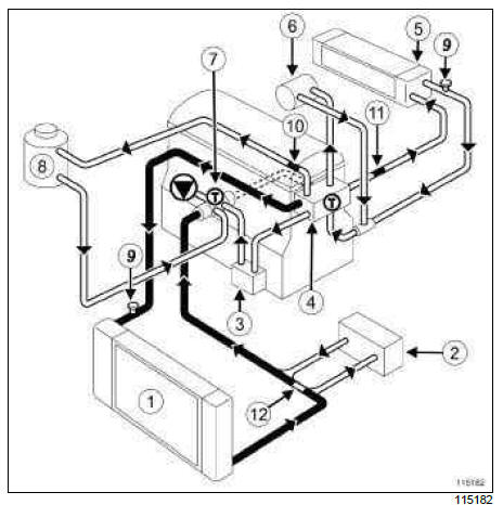
K9K, and 772
- Radiator
- Expansion bottle
- Heating elements
- Electric coolant pump
- Heater matrix
- Turbocharger
- Diesel fuel injector cooler on the catalytic pre-converter
- Exhaust gas cooler
- Thermostat
- Coolant pump
- Water-oil heat exchanger
- Bleed screw
- Bleed screw
- Bleed screw
- Choke
- Choke
- Choke
- Choke
READ NEXT:
 Cooling system: Draining - Refilling
IMPORTANT
The circuits are designed to be pressurised, so be
careful at high temperatures (risk of serious burns).
Do not remove the cap from the expansion bottle
while the engine is hot.
Take care
Cooling radiator: Removal - Refitting
D4F, and 740 or 742 or 764, and STANDARD HEATING
REMOVAL
I - REMOVAL PREPARATION OPERATION
Position the vehicle on a two-post lift (see Vehicle:
Towing and lifting) (MR 392, 02A, Lifting equipment
Coolant pump: Removal - Refitting
D4F, and 740 or 742 or 764
IMPORTANT
To avoid all risk of damage to the systems, apply
the safety and cleanliness instructions and operation
recommendations before carrying out any
repair:
(see 19A
SEE MORE:
Driving
The Renault Clio IV (2014-2019) offers a satisfying driving experience with its nimble handling and responsive performance. Its compact size and maneuverability make it well-suited for urban driving and tight parking spaces. The precise steering and suspension tuning provide a balanced and confident
Your comfort
The Renault Clio IV (2014-2019) is designed with your comfort in mind. It features a well-crafted interior with quality materials and thoughtful ergonomics. The seats offer excellent support and adjustability, providing a comfortable driving experience. The cabin is designed to minimize noise and vi
© 2016-2026 Copyright Renault Clio Owners Club - 0.0038
