Renault Clio: Engine stand: General description
IMPORTANT
Use a repair bench to ensure the positioning of the points and the geometry of the axle assemblies.
Note: The information contained in the following describes the general repair procedure for all vehicles having the same design for this part.
Before reading this general information, check that there are no special notes associated with this vehicle.
These special notes will be specified if applicable in other parts of this subsection dealing with the part.
Note: For a detailed description of a particular connection, see MR 400.
DESIGN OF THE STRUCTURAL COMPONENT
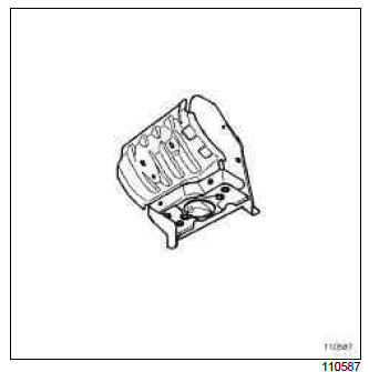
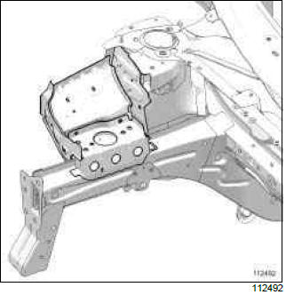
This is a basic part; it only functions as an engine mounting.
Engine stand: Description
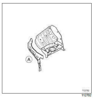
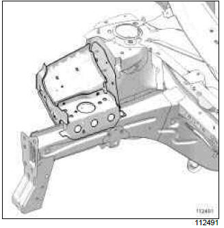
To replace this part, order, in addition, the front end side cross member (A).
There is only one way of replacing this part:
- complete replacement.
IMPORTANT
The straightening bench must be used.
I - COMPOSITION OF THE SPARE PART
Engine mounting, low torque
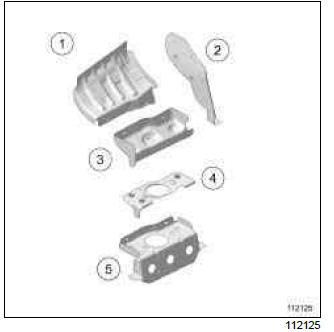
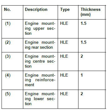
Engine mounting, high torque
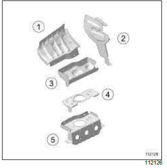
II - PART FITTED
Engine mounting, low torque
Engine mounting, high torque
WARNING
If the spot welds cannot be made as they were originally using an electrical spot welding machine, they should be replaced with plug welds after holes have been drilled in the first panel.
III - POSITIONING OF LOCAL ELECTRICAL EARTHS
For the earth stud fitting procedure (see 40A, General information, Earths on body: List and location of components, 40A-23)
READ NEXT:
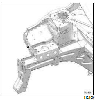
 Front half unit: Description
Left-hand side
Right-hand side
To replace this part, order the heater bulkhead reinforcement (A) and the
side member expanding insert (B).
There is only one way of replacing this part:
complete
Centre Lower Structure
Centre floor front side cross member: General
description
IMPORTANT
Use a repair bench to ensure the positioning of the
points and the geometry of the axle assemblies.
Note:
The information contained
Side Lower Structure
Sill panel: Description
B85 or K85
To replace this part, also order the expanding inserts
corresponding to each of the following cases.
The options for replacing this part are as follows:
partial
SEE MORE:
Expansion valve - intermediate pipe connecting pipe at the expansion valve outlet: Removal -
Refitting
F4R or K9K or M4R, and AIR CONDITIONING or CLIMATE CONTROL
IMPORTANT
To avoid all risk of damage to the systems, apply
the safety and cleanliness instructions and operation
recommendations before carrying out any
repair:
(see 62A, Air conditioning, Air conditioning:
Precautions for the repair, 6
Dehydrator reservoir - expansion valve connecting pipe: Removal - Refitting
AIR CONDITIONING or CLIMATE CONTROL
IMPORTANT
To avoid all risk of damage to the systems, apply
the safety and cleanliness instructions and operation
recommendations before carrying out any
repair:
(see 62A, Air conditioning, Air conditioning:
Precautions for the repair, 62A-1),
(see Vehicle: P
