Renault Clio: Exhaust gas recirculation solenoid valve: Removal - Refitting
K9K, and 764 or 766 or 768
REMOVAL
I - REMOVAL PREPARATION OPERATION
- Position the vehicle on a two-post lift (see Vehicle: Towing and lifting) (MR 392, 02A, Lifting equipment).
- Disconnect the battery (see Battery: Removal - Refitting) (MR 392, 80A, Battery).
- Remove:
- the engine undertray,
- the scuttle panel grille (see Scuttle panel grille: Removal - Refitting) (MR 393, 56A, Exterior equipment).
K9K, and 766 or 768
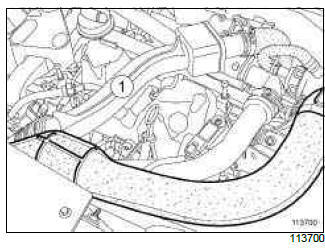
- Remove the air duct (1) between the intercooler and the turbocharger.
K9K, and 764
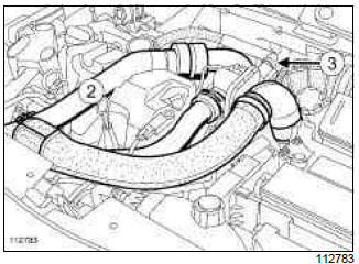
- Remove the air duct (2) between the intercooler and the turbocharger.
- Disconnect the oil vapour rebreathing pipe at (3) and move it aside.
II - REMOVAL OF PART CONCERNED
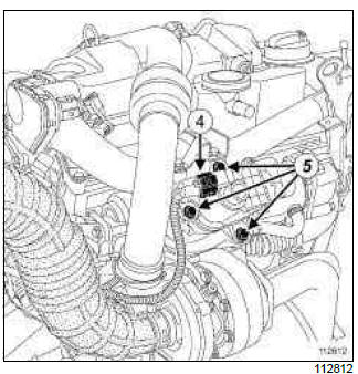
- Disconnect the connector (4) from the exhaust gas recirculation solenoid valve.
- Remove:
- the exhaust gas recirculation solenoid valve mounting bolts (5),
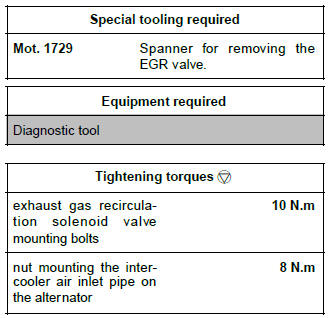
- the exhaust gas recirculation solenoid valve, using the tool (Mot. 1729),
- the seal of the exhaust gas recirculation solenoid valve.
Note: During removal of the solenoid valve using the (Mot. 1729), proceed slowly until the solenoid valve is loosened from its support to remove it.
REFITTING
I - REFITTING PREPARATION OPERATION
- Always replace the seal of the exhaust gas recirculation solenoid valve.
II - REFITTING PART CONCERNED
- Offer up the exhaust gas recirculation solenoid valve with a new seal.
- Torque tighten the exhaust gas recirculation solenoid valve mounting bolts (10 N.m).
III - FINAL OPERATION
K9K, and 764
- Reconnect the oil vapour rebreathing pipe.
- Loosen the mounting nut of the air pipe at the intercooler inlet on the alternator.
- Fit the air duct between the turbocharger and the intercooler air inlet pipe.
- Lock the air duct onto the turbocharger and the intercooler inlet air pipe.
- Tighten the bolt of the air duct on the rocker cover.
- Torque tighten the nut mounting the intercooler air inlet pipe on the alternator (8 N.m).
- Connect the battery (see Battery: Removal - Refitting) (MR 392, 80A, Battery).
Note: If replacing the exhaust gas recirculation solenoid valve, perform the necessary programming (see MR394, Section 13B, Fault finding - Replacement of components).
- Before restarting the engine, use the Diagnostic tool to clear any faults stored by the injection computer.
K9K, and 750 or 752
REMOVAL
I - REMOVAL PREPARATION OPERATION
- Disconnect the battery (see Battery: Removal - Refitting) (MR 392, 80A, Battery).
II - OPERATION FOR REMOVAL OF PART CONCERNED
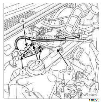
- Disconnect the connector (1) from the EGR solenoid valve.
- Remove:
- the nuts (2) from the strut on the EGR solenoid valve,
- the strut (3) on the EGR solenoid valve,
- the bolt from the EGR solenoid valve heat shield,
- the heat shield (4) from the EGR solenoid valve,
- the EGR solenoid valve,
- the seal between the EGR solenoid valve and the EGR solenoid valve mounting.
Note: Clean the exhaust gas recirculation solenoid valve if it is reinitialised (see Exhaust gas recirculation solenoid valve: Cleaning) (Technical Note 3916A, 14A, Emission control).
REFITTING
I - REFITTING PREPARATION OPERATION
- Always replace the seal between the EGR solenoid valve and the EGR solenoid valve mounting.
II - REFITTING OPERATION FOR PART CONCERNED
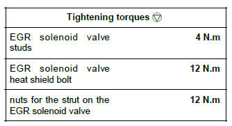
- Refit the EGR solenoid valve studs, if necessary.
- Torque tighten the EGR solenoid valve studs (4 N.m), if necessary.
- Refit:
- the seal between the EGR solenoid valve and the EGR solenoid valve mounting,
- the EGR solenoid valve,
- the EGR solenoid valve heat shield,
- the bolt from the EGR solenoid valve heat shield,
- the strut on the EGR solenoid valve,
- the nuts from the strut on the EGR solenoid valve,
- Torque tighten:
- the EGR solenoid valve heat shield bolt (12 N.m),
- the nuts for the strut on the EGR solenoid valve (12 N.m).
- Connect the EGR solenoid valve connector.
III - FINAL OPERATION
- Connect the battery (see Battery: Removal - Refitting) (MR 392, 80A, Battery).
Note: If replacing the exhaust gas recirculation solenoid valve, perform the necessary programming (see MR394, Section 13B, Fault finding - Replacement of components).

