Renault Clio: Fuel vapour recirculation circuit: Function
D4F or F4R or K4J or K4M or M4R
WARNING
The breather must not be blocked during normal engine operation.
The tank is vented through the fuel vapour absorber.
Fuel vapour is trapped by the active carbon contained in the absorber as it passes through.
Fuel vapour trapped in the absorber is eliminated and burnt by the engine.
To do this, the solenoid valve is used to connect the fuel vapour absorber and the inlet manifold. This solenoid valve is located on the right-hand shock absorber turret or on the inlet manifold (M4R engine).
The principle behind the solenoid valve is to open a passage of variable size (according to the opening cyclic ratio signal sent by the injection computer).
The variation in the passage opened for fuel vapour in the solenoid valve results from the balance between the magnetic field created by the supply to the winding and the return spring force attempting to close the solenoid valve.
Fuel vapour recirculation circuit: Operating diagram
D4F or F4R or K4J or K4M or M4R
OPERATING DIAGRAM OF THE CIRCUIT
F4R or K4J or K4M or M4R - D4F, and 740 or 742 or 764
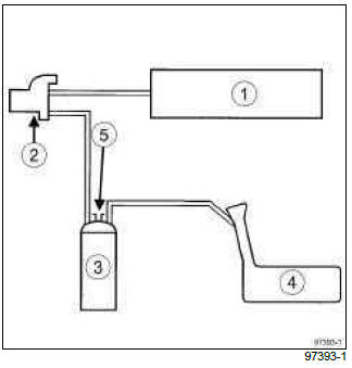
- Inlet distributor
- Fuel vapour absorber bleed solenoid valve
- Petrol vapour absorber
- Tank
- Fresh air vent
D4F, and 784 or 786
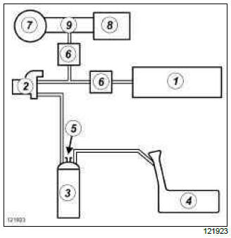
- Inlet distributor
- Fuel vapour absorber bleed solenoid valve
- Fuel vapour absorber
- Tank
- Fresh air vent
- Anti-return valve
- Turbocharger
- Air filter unit
- Air filter box air outlet pipe
Fuel vapour recirculation circuit: Check
F4R or K4J or K4M or M4R - D4F

I - CHECKING THE OPERATION OF THE FUEL VAPOUR ABSORBER BLEED
Note: A fault with this system may result in rough idling or the engine stalling.
F4R or K4J or K4M or M4R - D4F, and 740 or 742 or 764
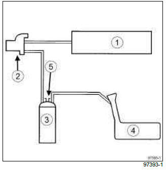
- Inlet distributor
- Fuel vapour absorber bleed solenoid valve
- Petrol vapour absorber
- Tank
- Fresh air vent
- Check the condition of the pipes to the tank.
D4F, and 784 or 786
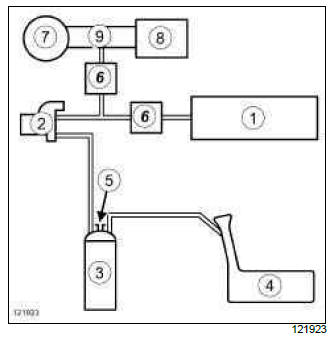
- Inlet distributor
- Fuel vapour absorber bleed solenoid valve
- Petrol vapour absorber
- Tank
- Fresh air vent
- Anti-return valve
- Turbocharger
- Air filter unit
- Air filter box air outlet pipe
- Check the condition of the pipes to the tank.
II - FUEL VAPOUR ABSORBER BLEED CONDITIONS
- The fuel vapour absorber bleed solenoid valve is
controlled by the petrol injection computer.
During " on board diagnostic " fault finding, fuel vapour absorber bleeding is not authorised.
The opening cyclic ratio of the fuel vapour absorber bleed solenoid valve can be viewed on the Diagnostic tool by reading parameter " fuel vapour absorber bleed solenoid valve OCR " .
The solenoid valve is closed for a value below 1.2%.
Fuel vapour absorber: Removal - Refitting
D4F or F4R or K4J or K4M or M4R
IMPORTANT
During this operation, be sure to:
- be careful of fuel splashes when disconnecting the union.
IMPORTANT
Wear latex gloves during the operation.
WARNING
To avoid any corrosion or damage, protect the areas on which fuel is likely to run.
REMOVAL
I - REMOVAL PREPARATION OPERATION
- Position the vehicle on a two-post lift (see Vehicle: Towing and lifting) (MR 392, 02A, Lifting equipment).
- Disconnect the battery (see Battery: Removal - Refitting) (MR 392, 80A, Battery).
II - OPERATION FOR REMOVAL OF PART CONCERNED
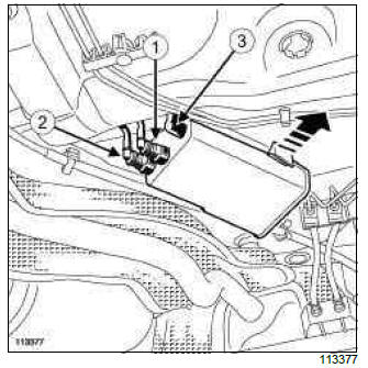
- Remove the absorber from the fuel tank retaining notch by pushing it in the direction of the arrow.
- Disconnect:
- the tank vapour inlet pipe (1),
- the pipe (2) circulating vapours to the solenoid valve,
- the breather pipe (3).
- Remove the fuel vapour absorber.
REFITTING
I - REFITTING OPERATION FOR PART CONCERNED
- Refit the fuel vapour absorber.
- Connect:
- the breather pipe,
- the pipe taking the fuel vapours to the solenoid valve,
- the pipe bringing the fuel vapour from the tank.
- Refit the absorber in the fuel tank retaining notch.
II - FINAL OPERATION.
- Connect the battery (see Battery: Removal - Refitting) (MR 392, 80A, Battery).
Fuel vapour absorber: Check
D4F or F4R or K4J or K4M or M4R

I - CHECKING THE FUEL VAPOUR ABSORBER
- On the fuel vapour absorber, plug the circuit coming from the fuel tank.
- Connect a pressure gauge on the Mot. 1311-01 to the absorber breather outlet.
- With the engine at idle speed, check that no vacuum is present at the absorber breather outlet. In the same way, the control value read by the Diagnostic tool in parameter " fuel vapour absorber bleed solenoid valve OCR " remains at least X less than or equal to 1.5 %.
Is there a vacuum?
- YES: with the ignition off, use a vacuum pump to apply
a vacuum of 500 mbar to the solenoid valve outlet.
The vacuum pressure should not vary by more than 10 mbar over 30 seconds.
Does the pressure vary?
- Yes: the solenoid valve is faulty, replace it.
- No: there is an electrical fault, check the circuit.
- NO: in bleeding condition (see 14A, Antipollution, Fuel vapour recirculation circuit: Check, 14A-25), the vacuum must be increased. In the same time, the value of the parameter on the Diagnostic tool increases.
II - CHECKING THE FUEL VAPOUR ABSORBER TANK CONNECTION
- Check this connection by connecting a vacuum pump to the pipe going to the absorber.

