Renault Clio: Gear control: List and location of components
JH3 or JR5
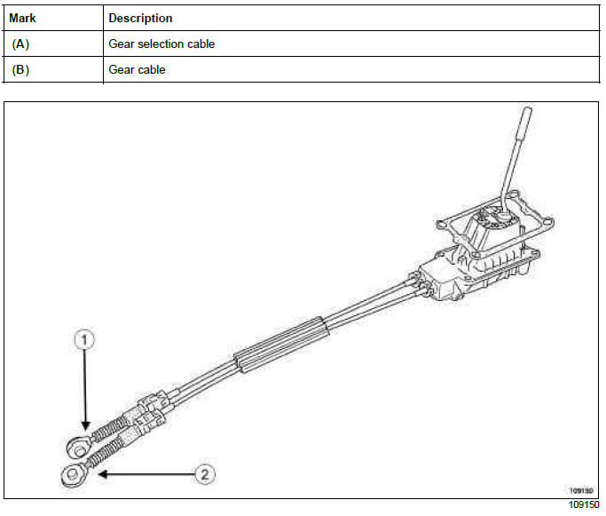
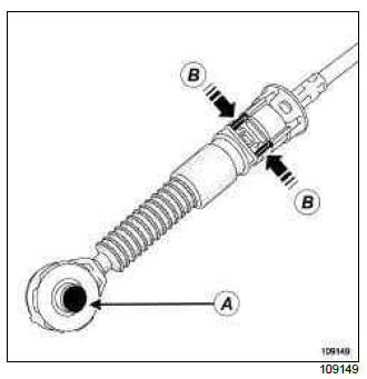
- Press at " A " to separate the gearbox control cables from the anchoring ball joint on the gearbox
- Press at " B " to separate the gearbox control cables from the sheath stops on the gearbox
TL4
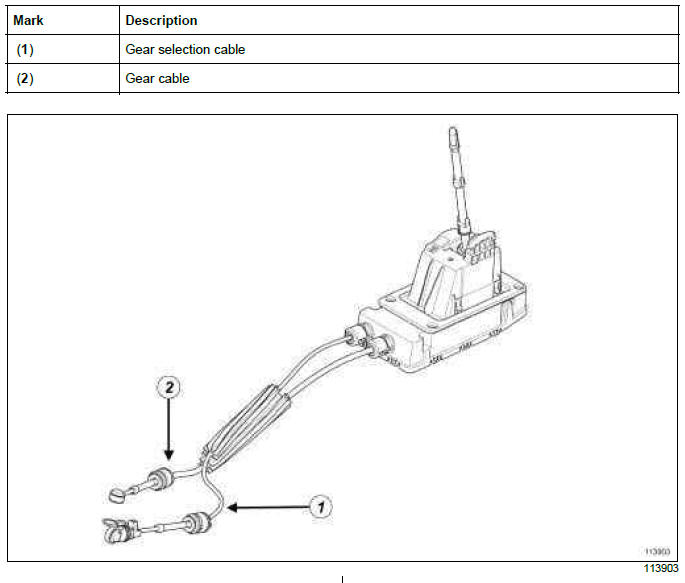
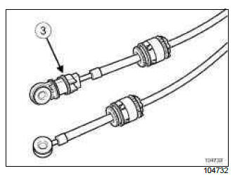
Note: The external control of the TL4 gearbox has an adjusting system (3) on the selection cable.
DP0
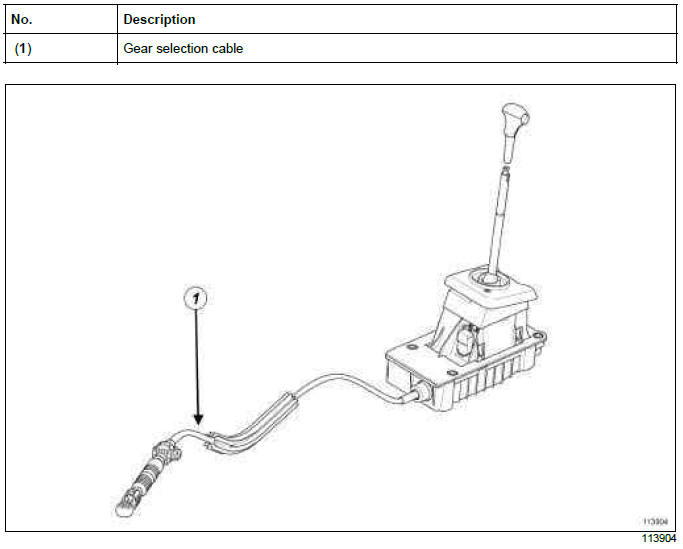
Gear control unit: Removal - Refitting
JH3 or JR5 or TL4
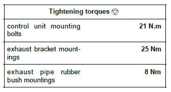
REMOVAL
I - REMOVAL PREPARATION OPERATION
- Position the vehicle on a two-post lift (see Vehicle: Towing and lifting) (MR 392, 02A, Lifting equipment).
K4J or K4M or K9K
- Remove:
- the battery (see Battery: Removal - Refitting) (MR 392, 80A, Battery),
- the air filter unit (see Air filter unit: Removal - Refitting) (MR 392, 12A, Fuel mixture).
D4F
- Disconnect the battery (see Battery: Removal - Refitting) (MR 392, 80A, Battery).
- Remove the engine undertray.

- Remove:
- the exhaust bracket mountings,
- the exhaust pipe rubber bush mountings (1).
- Let the exhaust pipe rest on the rear axle.
Note: The oxygen sensor wiring harness must not be under tension.
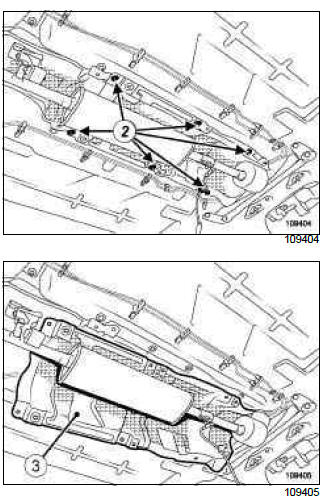
- Remove:
- the heat shield mountings (2),
- heat shield (3).
II - OPERATION FOR REMOVAL OF PART CONCERNED
TL4
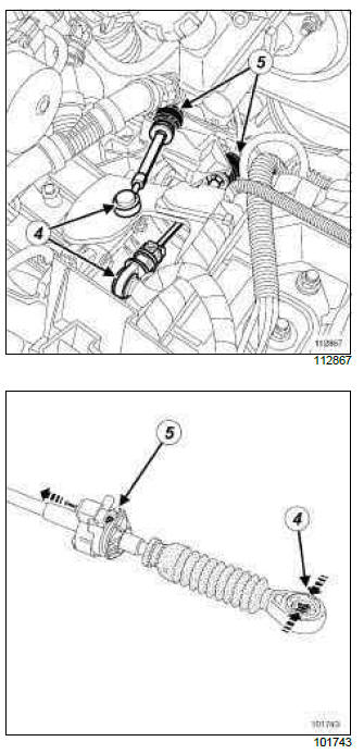
- Unclip the two gear lever cables on the gearbox at:
- the anchoring ball joints (4),
- the cable sleeve stops (5).
JH3 or JR5
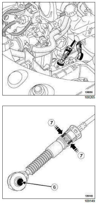
- Unclip:
- the gear control cables from the gearbox by pressing at (6),
- the gearbox control cable sleeve stops by pulling the catch (7).
- Remove the centre console (see Centre console: Removal - Refitting) (MR 393, 57A, Interior equipment).
- Unclip the gear lever gaiter with its knob.
- Remove the soundproofing pad covering the gear control unit.
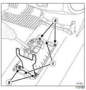
- Remove the gear selection unit mountings (8).
- Unclip the gear selection unit from the floor at (9).
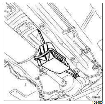
- Lower the gearbox control unit so it is resting on the exhaust.
- Remove the gear control unit by feeding it out between the exhaust and the tunnel.
REFITTING
I - REFITTING PREPARATION OPERATION
- The external control unit and the selector levers on
the gearbox must be in the neutral position to facilitate
attachment of the control cables to the gearbox.
When refitting the exhaust pipe rubber mounting bushes, make sure that they are perfectly in line with the axis of the vehicle.
There is no system to adjust the control cables on JH3 and JR5 gearboxes.
II - REFITTING OPERATION FOR PART CONCERNED
- Reposition the gear control unit by feeding it between the exhaust and the tunnel.
- Reclip the gear control unit to the floor.
- Refit the gear control unit mountings.
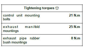
- Torque tighten the control unit mounting bolts (21 N.m).
TL4
- Adjust the selection cable (see 37A, Mechanical component controls, Manual gear control: Adjustment, 37A-1).
- Refit the soundproofing covering the gear control unit.
- Refit the centre console (see Centre console: Removal - Refitting) (MR 393, 57A, Interior equipment).
- Reclip the gear lever gaiter with its knob.
- Reclip:
- the gearbox control cable sleeve stops,
- the gearbox control cables.
III - FINAL OPERATION.
- Refit:
- the heat shield,
- the heat shield mountings.
- Refit:
- the exhaust pipe at the silencer,
- the mountings from the exhaust pipe rubber mounting bushes,
- the exhaust bracket mountings.
- Tighten to torque:
- the exhaust bracket mountings (25 Nm),
- the exhaust pipe rubber bush mountings (8 Nm).
K4J or K4M or K9K
- Refit:
- the engine undertray,
- the air filter box (see Air filter unit: Removal - Refitting) (MR 392, 12A, Fuel mixture),
- the battery (see Battery: Removal - Refitting) (MR 392, 80A, Battery).
D4F
- Refit the engine undertray.
- Connect the battery.
DP0
REMOVAL
I - REMOVAL PREPARATION OPERATION
- Position the vehicle on a two-post lift (see Vehicle: Towing and lifting) (MR 392, 02A, Lifting equipment).
- Move the gear lever to the Neutral position.
- Remove:
- the battery (see Battery: Removal - Refitting) (MR 392, 80A, Battery),
- the air filter box (see Air filter unit: Removal - Refitting) (MR 392, 12A, Fuel mixture),
- the engine undertray.
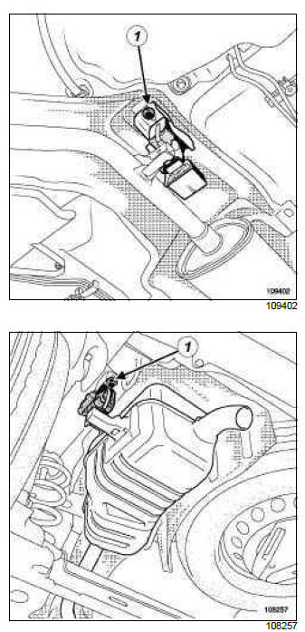
- Remove:
- the exhaust pipe rubber bush mountings (1),
- the exhaust manifold mountings.
- Let the exhaust pipe rest on the rear axle.
Note: The oxygen sensor wiring harness must not be under tension.
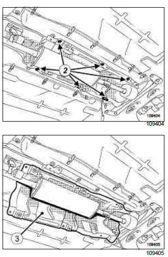
- Remove:
- the heat shield mountings (2),
- the heat shield (3).
II - OPERATION FOR REMOVAL OF PART CONCERNED
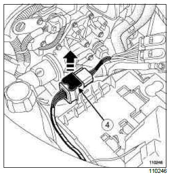
- Disconnect the automatic gearbox wiring harness connector by pulling out the slide (4).
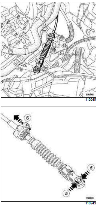
- Remove:
- the multifunction switch control cable ball joint by pressing at (5),
- the control cable sheath stop from the modular connector support by pulling the catch at (6).
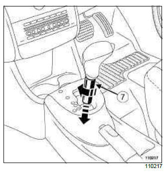
- Turn the part (7) a quarter of a turn.
- Lower the part (7).
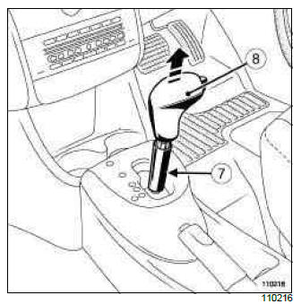
- Remove:
- the control lever knob (8), lifting it up and off,
- the part (7),
- the centre console (see Centre console: Removal - Refitting) (MR 393, 57A, Interior equipment),
- the soundproofing pad covering the gear control unit.
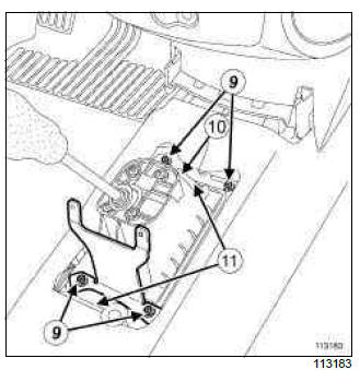
- Remove the gear selection unit mountings (9).
- Disconnect the control unit connector (10).
- Unclip the gear selection unit from the floor at (11).
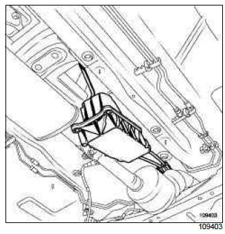
- Lower the gearbox control unit so it is resting on the exhaust.
- Remove the gear control unit by feeding it out between the exhaust and the tunnel.
REFITTING
I - REFITTING PREPARATION OPERATION
- When refitting the exhaust pipe rubber mountings, make sure that they are perfectly in line with the axis of the vehicle.
II - REFITTING OPERATION FOR PART CONCERNED
- Reposition the gear control unit by feeding it between the exhaust and the tunnel.
- Reclip the gear control unit to the floor.
- Refit the gear control unit mountings.
- Torque tighten the control unit mounting bolts (21 N.m).
- Connect the control unit connector.
- Refit:
- the soundproofing pad covering the gear control unit,
- the centre console (see Centre console: Removal - Refitting) (MR 393, 57A, Interior equipment),
- the part (7),
- the control lever knob.
- Turn the part (7) a quarter of a turn.
WARNING
- Mark the position of the gear lever clearly before starting the operation: if this is not possible, put the selector and the multifunction switch in the Neutral position.

- Push the clip (13) forward.
- Lift the clip (14) upward.
- Clip the control cable into the sleeve stop.
- Clip the cable end piece to the multifunction switch ball joint.
- Fasten the clip (13) to lock the cable end piece.
- Check that the system and gear selection are working correctly.
- Connect the automatic gearbox wiring harness connector.
III - FINAL OPERATION
- Refit:
- the heat shield,
- the heat shield mountings.
- Refit:
- the exhaust pipe at the silencer,
- the exhaust manifold mountings,
- the exhaust pipe rubber bush mountings.
- Torque tighten:
- the exhaust manifold mountings (25 N.m),
- the exhaust pipe rubber bush mountings (8 N.m).
- Refit:
- the engine undertray,
- the air filter box (see Air filter unit: Removal - Refitting) (MR 392, 12A, Fuel mixture),
- the battery (see Battery: Removal - Refitting) (MR 392, 80A, Battery).

