Renault Clio: K9K, and 750 or 752
REMOVAL
I - REMOVAL PREPARATION OPERATION
- Disconnect the battery (see Battery: Removal - Refitting) (MR 392, 80A, Battery).
K9K, and 750
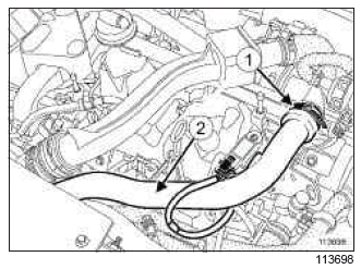
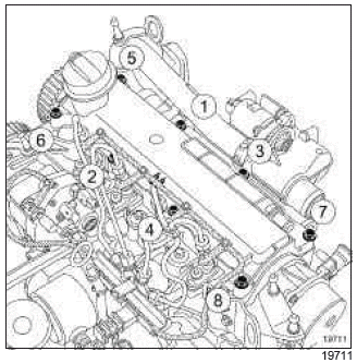
- Undo the clip (1) from the intercooler outlet pipe.
- Move the intercooler outlet air pipe to one side (2).
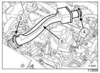
- Remove the turbocharger outlet air pipe retaining pin (3).
- Loosen the turbocharger outlet air pipe clip (4).
- Remove the turbocharger air outlet pipe (5).
- Disconnect:
- the oil vapour rebreathing pipe,
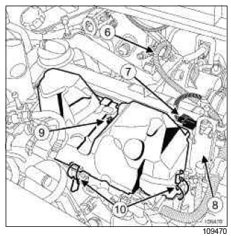
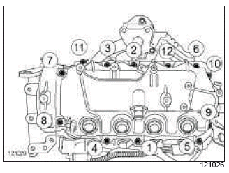
- the connector (6) from the EGR solenoid valve,
- the air pressure sensor connector (7).
- Unclip the breather pipe from the gearbox.
- Remove:
- the lifting eye bolts (8) on the gearbox side,
- the gearbox side lifting eye.
- Move the wiring harness to one side.
- Unclip the clips (9) from the injector rail protector.
- Remove:
- the injector rail protector bolt (10),
- the injector rail protector.
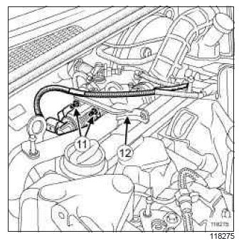
- Remove:
- the nuts (11) from the EGR solenoid valve strut (12),
- the strut on the EGR solenoid valve.
II - OPERATION FOR REMOVAL OF PART CONCERNED
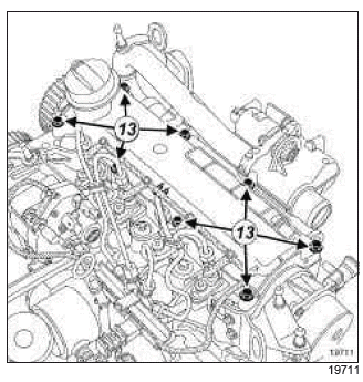
- Remove:
- the rocker cover bolts (13),
- the rocker cover.
REFITTING
I - REFITTING PREPARATION OPERATION
WARNING
The joint faces must be clean, dry and free from grease (avoid finger marks).
WARNING
Applying excess sealant could cause it to be squeezed out when parts are tightened. A mixture of sealant and fluid could damage certain components (engine, radiator, etc.).
- Apply RESIN ADHESIVE, 2 mm in diameter.
II - REFITTING OPERATION FOR PART CONCERNED
- Refit the rocker cover, fitted with a new gasket.
- Fit without tightening the rocker cover bolts.
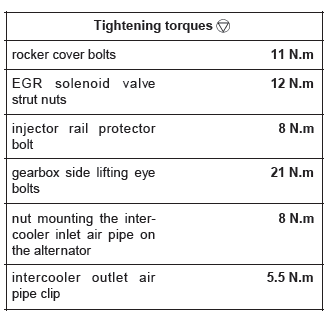
- Tighten to torque and in order the rocker cover bolts (11 N.m).
III - FINAL OPERATION
- Refit:
- the strut on the EGR solenoid valve,
- the EGR solenoid valve strut nuts.
- Tighten to torque the EGR solenoid valve strut nuts (12 N.m).
- Refit:
- the injector rail protector,
- the injector rail protector bolt.
- Torque tighten the injector rail protector bolt (8 N.m).
- Clip the clips onto the injector rail protector.
- Refit:
- the gearbox side lifting eye,
- the gearbox side lifting eye bolts.
- Fit the wiring harness.
- Connect:
- the air pressure sensor connector.
- the exhaust gas recirculation solenoid valve connector,
- the oil vapour rebreathing pipe.
- Clip the breather pipe to the gearbox.
- Tighten to torque the gearbox side lifting eye bolts (21 N.m).
K9K, and 750
- Loosen the intercooler inlet air pipe nut on the alternator.
- Fit:
- the turbocharger air outlet pipe,
- the turbocharger outlet air pipe retaining pins.
- Click into place the turbocharger outlet air pipe.
- Tighten the turbocharger outlet air pipe bolt on the rocker cover.
- Torque tighten the nut mounting the intercooler inlet air pipe on the alternator (8 N.m).
- Fit the intercooler outlet air pipe.
- Torque tighten the intercooler outlet air pipe clip (5.5 N.m).
- Connect the battery (see Battery: Removal - Refitting) (MR 392, 80A, Battery).
D4F, and 784 or 786
REMOVAL
I - REMOVAL PREPARATION OPERATION
- Disconnect the battery (see Battery: Removal - Refitting) (MR 392, 80A, Battery).
- Remove the front engine cover
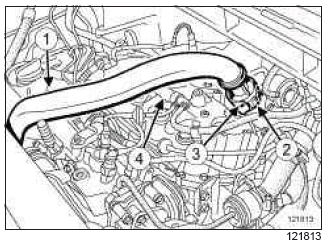
- Remove the bolt (1) from the intercooler air inlet pipe on the intake distributor.
- Remove the intercooler air inlet pipe clip (2) on the turbocharger.
Note: If the clip (3) is removed from the heat resistant protector, the latter must be replaced.
- Move the intercooler inlet air pipe to one side.
- Disconnect the oil vapour rebreathing circuit union (4).
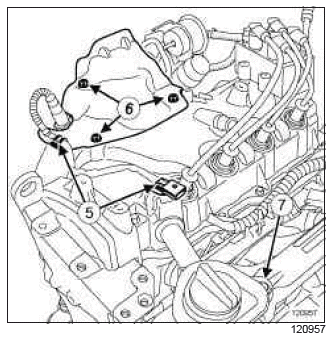
- Unpick the wiring harness from the upstream oxygen sensor at (5).
- Remove:
- the bolts (6) from the heat shield,
- the heat shield,
- the filler neck bolt (7),
- the filler neck,
- the ignition coil (see 17A, Ignition, Coils: Removal - Refitting, 17A-2).
II - OPERATION FOR REMOVAL OF PART CONCERNED
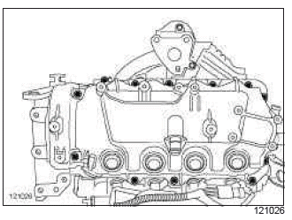
- Remove:
- the rocker cover bolts,
- the rocker cover,
- the rocker cover gasket.
REFITTING
I - REFITTING PREPARATIONS OPERATION
- Clean the joint faces using SUPER CLEANING AGENT FOR JOINT FACES (see Vehicle: Parts and consumables for the repair) (MR 392, 04B, Consumables - Products) to dissolve the part of the seal which is still attached.
WARNING
Do not allow this product to drip onto the paintwork.
Clean the cylinder head carefully to prevent foreign bodies from entering the oil supply and return galleries.
Failure to follow this advice could lead to the blocking of the various oil inlet galleries, which would quickly result in engine damage.
- Replace the rocker cover seal.
II - REFITTING OPERATION FOR PART CONCERNED
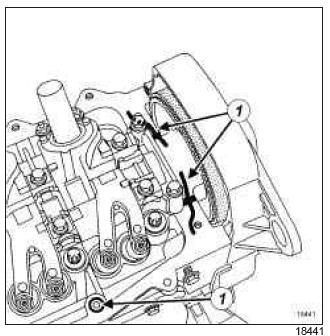
- Apply beads (1) of MASTIXO (see Vehicle: Parts and consumables for the repair) (MR 392, 04B, Consumables - Products) around the 4 rocker cover bolts (lower bolts, exhaust side) and on camshaft bearing no.5.
WARNING
Applying excess sealant could cause it to be squeezed out when parts are tightened. A mixture of sealant and fluid could damage certain components (engine, radiator, etc.).
- Fit the new rocker cover seal, starting with bearing No. 5, then gradually insert the seal studs as the rocker cover fits into the groove.
- Refit:
- the rocker cover fitted with a new seal,
- the rocker cover bolts.
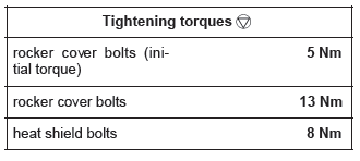
- Pretighten to torque and in order the rocker cover bolts (initial torque) (5 Nm).
- Torque tighten in order the rocker cover bolts (13 Nm).
III - FINAL OPERATION.
- Remove:
- the ignition coil (see 17A, Ignition, Coils: Removal - Refitting, 17A-2),
- the filler neck,
- the filler neck bolt,
- the heat shield,
- the heat shield bolts.
- Torque tighten the heat shield bolts (8 Nm).
- Connect the oil vapour rebreathing circuit union.
- Clip the upstream oxygen sensor wiring harness into place.
- Refit the intercooler air inlet pipe.
- Clip the intercooler air inlet pipe onto the turbocharger.
- Refit the intercooler air inlet pipe bolt on the intake distributor.
- Refit the engine cover.
- Connect the battery (see Battery: Removal - Refitting) (MR 392, 80A, Battery).
READ NEXT:
 Camshaft dephaser:
Function
Camshaft dephaser:
Function
I - SPECIAL NOTES
Its role is to modify the valve timing.
To improve cylinder filling at all engine speeds, the engine is fitted with an
inlet camshaft dephaser (1).
Dephasing at the moment when th
Camshaft dephaser:
Removal - Refitting
M4R
The engine and gearbox assembly must be removed
to remove/refit the camshaft dephaser (see
10A, Engine and cylinder block assembly, Engine
- gearbox assembly: Removal - Refitting, 10A-112).
Camshaft: Removal -
Refitting
D4F, and 740 or 742 or 764
REMOVAL
I - REMOVAL PREPARATION OPERATION
Position the vehicle on a two-post lift (see Vehicle:
Towing and lifting) (MR 392, 02A, Lifting equipment).
Disconnect the bat
SEE MORE:
Driving
The Renault Clio IV (2014-2019) offers a satisfying driving experience with its nimble handling and responsive performance. Its compact size and maneuverability make it well-suited for urban driving and tight parking spaces. The precise steering and suspension tuning provide a balanced and confident
Your comfort
The Renault Clio IV (2014-2019) is designed with your comfort in mind. It features a well-crafted interior with quality materials and thoughtful ergonomics. The seats offer excellent support and adjustability, providing a comfortable driving experience. The cabin is designed to minimize noise and vi
