Renault Clio: Vehicle on repair bench: Description
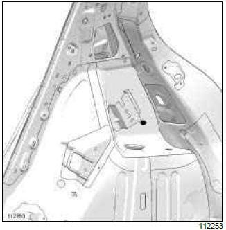
I - MAIN REFERENCE POINTS BEFORE TRIM-SETTING
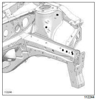
1 - Front sub-frame in place
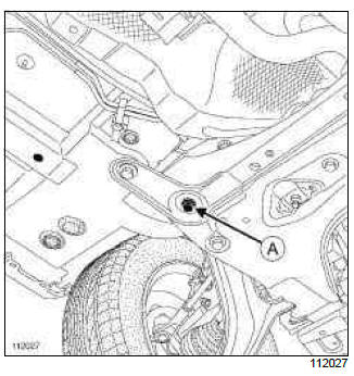
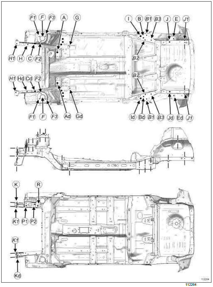
The jig crowns the front sub-frame rear mounting bolt (A).
Use this situation for a rear impact or a light frontal impact without removal of the mechanical components.
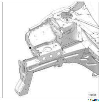
2 - Front mechanical components removed
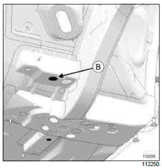
The jig rests under the sub-frame mounting unit and is centred in the threaded hole (B).
Use this situation for a frontal impact with removal of the mechanical components.
Note: If it is suspected that one of these points may be deformed, use two additional points located in an area not affected by the impact in order to confirm trim-setting.
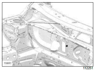
II - SECONDARY FRONT TRIM-SETTING REFERENCE POINT
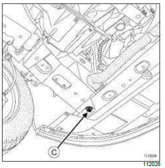
The body jig covers radiator mounting cross member mounting bolt (C).
Use this situation to confirm the trim-setting following a rear impact, (e.g.: to replace a rear side member assembly).
It is used to confirm the vehicle level in case of doubt about the deformation of a main rear reference point.
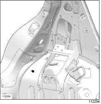
III - MAIN REAR TRIM-SETTING REFERENCE POINT
1 - Rear mechanical components in place
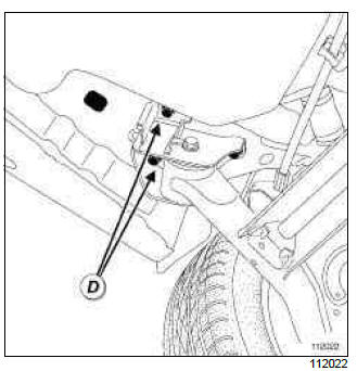
The jig supports the underside of the rear axle fork and is centred in rear axle mounting bolt tapped hole (D).
Use this situation for a frontal impact or a light rear impact.
2 - Rear mechanical components removed
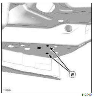
The jig rests under the rear side member and is centred in the tapped hole (E).
Use this situation for a rear impact with removal of the mechanical components.
Note: If it is suspected that one of these points may be deformed, use two additional points located in an area not affected by the impact in order to confirm trim-setting.
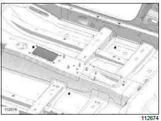
IV - SECONDARY REAR TRIM-SETTING REFERENCE POINT
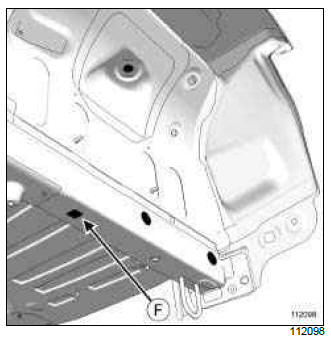
The jig rests under the rear side member and is positioned in square hole (F).
Use this situation to confirm the trim-setting following a frontal impact (e.g.: to replace a complete front half unit).
It is used to confirm the vehicle trim setting in case of doubt about the deformation of a main front reference point.
V - FITTING THE VEHICLE ANCHORING KIT
1 - At the front
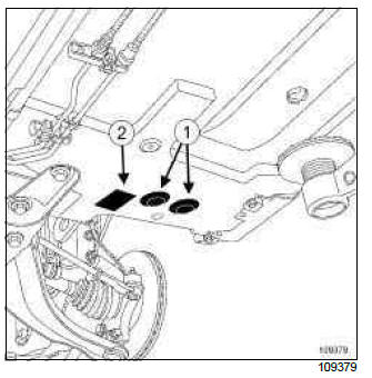
- Remove
- the wheels,
- the blanking covers (1) and (2).
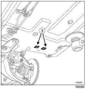
Fit inserts (3).
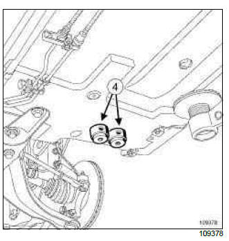
- Fit the mountings (4) without tightening them.
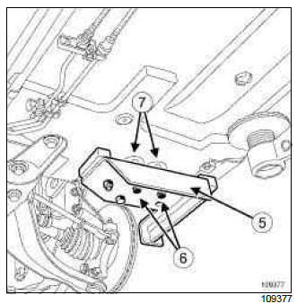
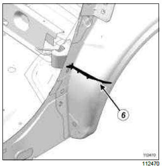
Position the (5) and secure it with the bolts (6).
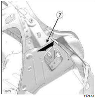
Finish the tightening operation with the mountings (7).
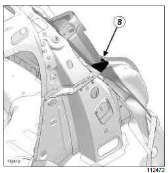
2 - At the rear
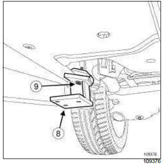
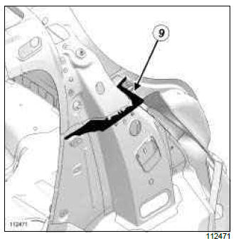
Position the clamp (8) on the horizontal flange on the rear section of the sill panel and lock it with the bolt (9).
Position the vehicle on the body jig bench clamps.
WARNING
The sub-frame on this vehicle is protected by products which guarantee the 12-year anti-corrosion warranty.
After the operation, protect the hollow sections of the front side cross members and refit the blanking covers. Replace any damaged blanking covers.
Re-apply the anti-gravel protection if it has deteriorated.
Subframe: Specifications
K85
B85 or C85 or S85
Hollow section inserts: List and location of components
B85
C85 or S85
K85
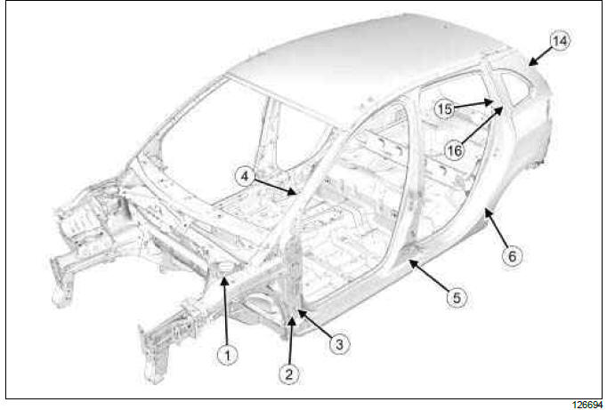
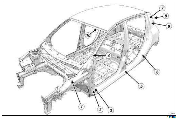
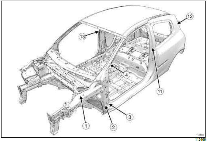
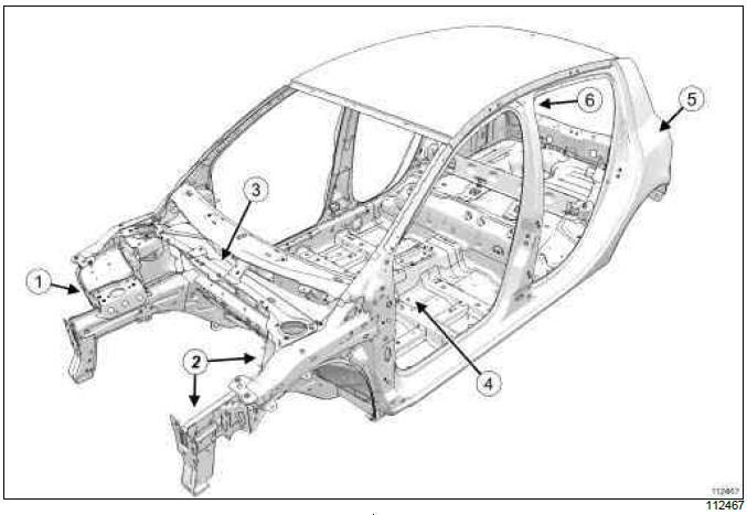
Front wing upper mounting bracket insert (1).
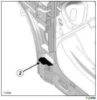
Exterior A-pillar insert (2).
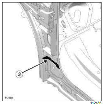
Interior A-pillar insert (3).
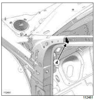
A-pillar insert (4).
B85 or K85
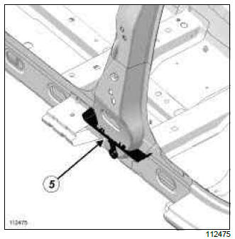
B-pillar insert (5).
Wheel arch insert (6).
B85
Interior quarter panel insert (7).
Rear quarter panel insert (8).
Exterior quarter panel insert (9).
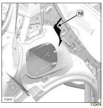
Right-hand quarter panel insert (10).
C85 or S85
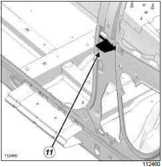
B-pillar insert (11).
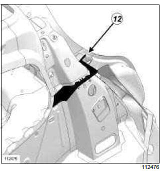
Exterior quarter panel insert (12).
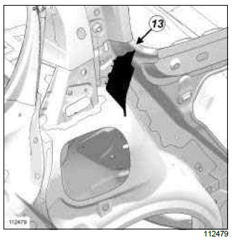
Quarter panel insert (13).
K85
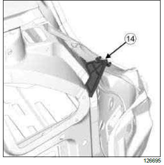
Rear quarter panel insert (14).
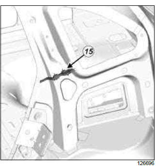
Front quarter panel insert (15).
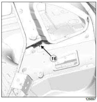
Interior quarter panel insert (16).
Earths on body: List and location of components
WARNING
To avoid damaging the vehicle's electrical and electronic components, disconnect the earths of any wiring near the weld area.
Position the welding machine earth as close as possible to the weld zone (see MR 400).
For the earth stud replacement procedure, see MR 400.
B85
C85 or S85
K85
DETAILED VIEW OF THE POSITION OF EARTHS ON THE VEHICLE
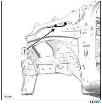
Earth stud on the right-hand front end side cross member (1).
Earth studs on left-hand front half unit (2).
Earth stud on bulkhead (3).
Earth studs on left and right-hand centre floor, side section, and tunnel (4).
B85
Left side
Earth stud on left-hand inner wheel arch (5).
Right-hand side
Earth stud on right-hand inner wheel arch.
C85 or S85
Left side
Earth stud on left-hand inner wheel arch (7).
Right-hand side
Earth stud on right-hand inner wheel arch (8).
K85
Earth stud on left-hand rear wheel arch (9).
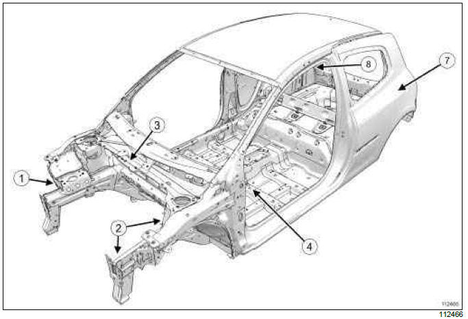
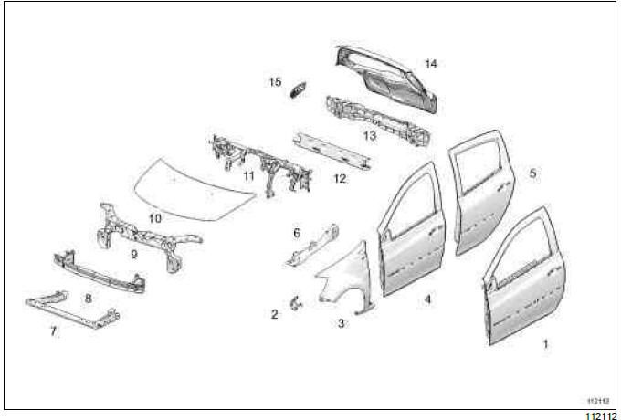
Vehicle structure, removable section: Description
STRUCTURE WHICH CAN BE DISMANTLED
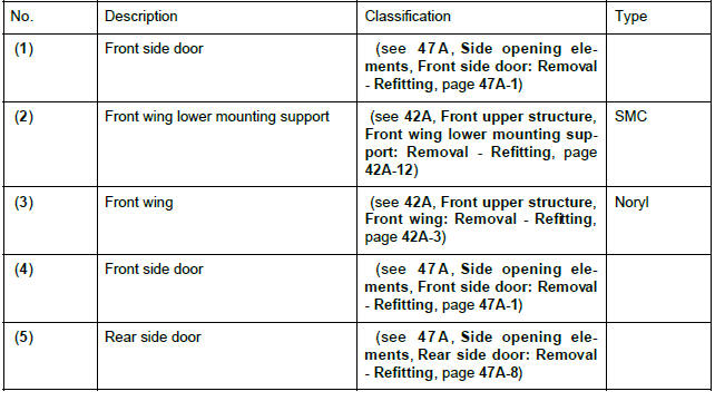
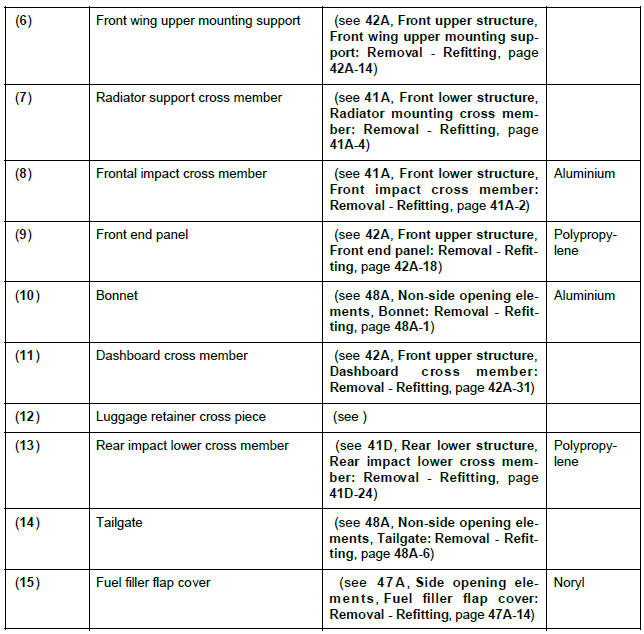
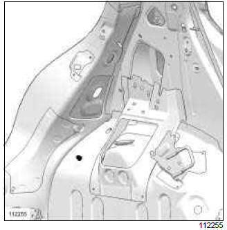
Vehicle structure, front section: Description
FRONT STRUCTURE
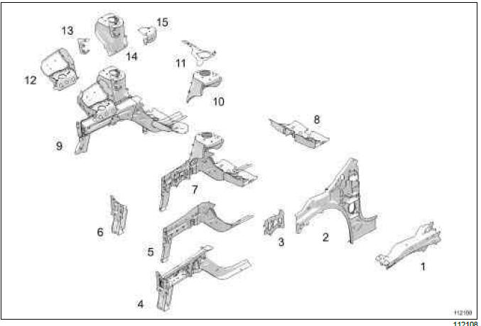
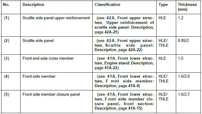
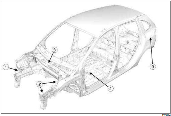
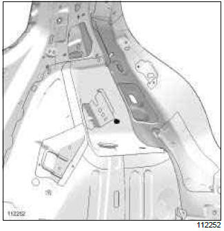
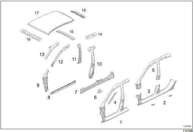
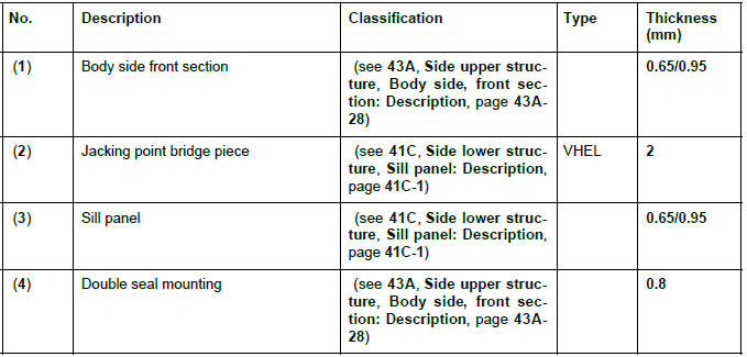
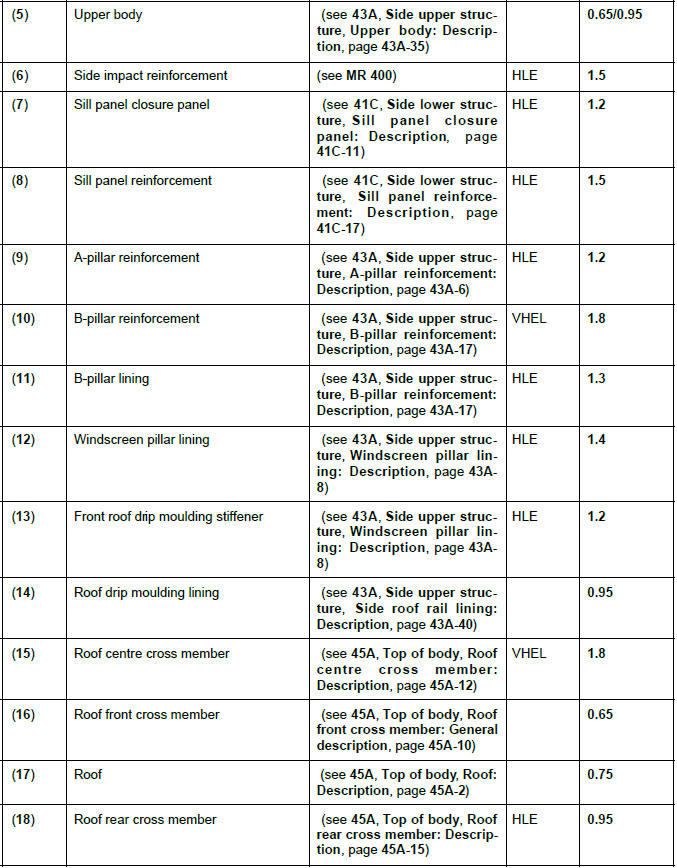
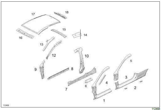
Vehicle structure, side section: Description
SIDE STRUCTURE
B85 or K85
C85 or S85
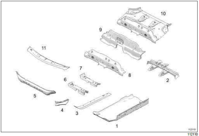
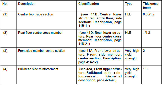
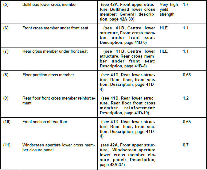
Vehicle structure, centre section: Description
CENTRAL STRUCTURE
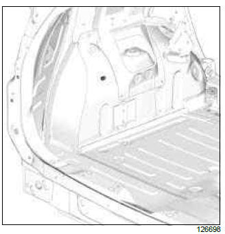
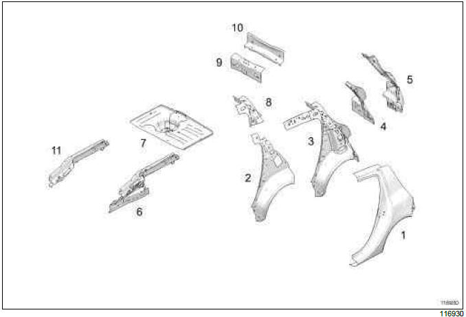
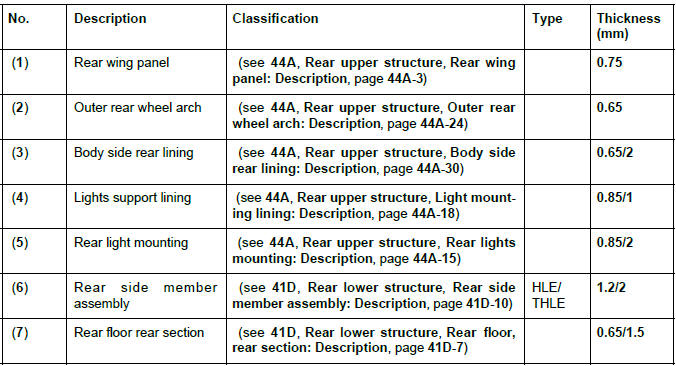
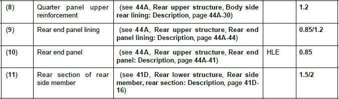
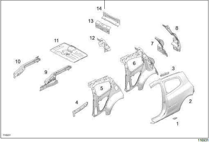
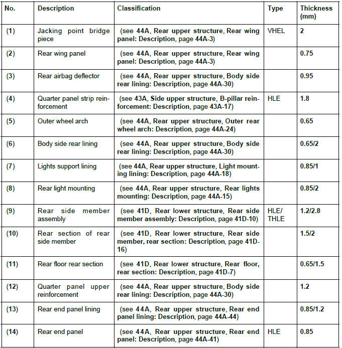
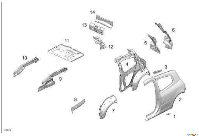
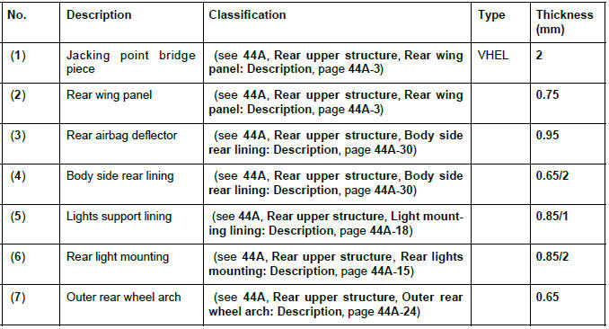
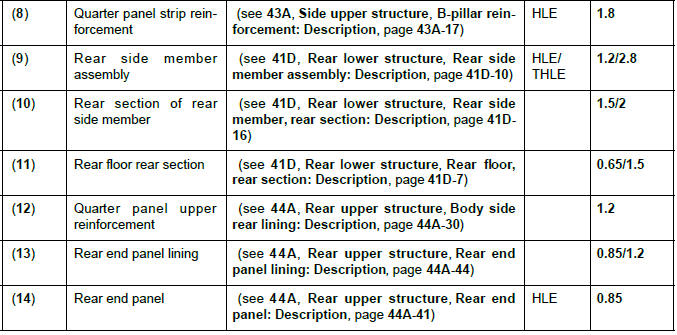
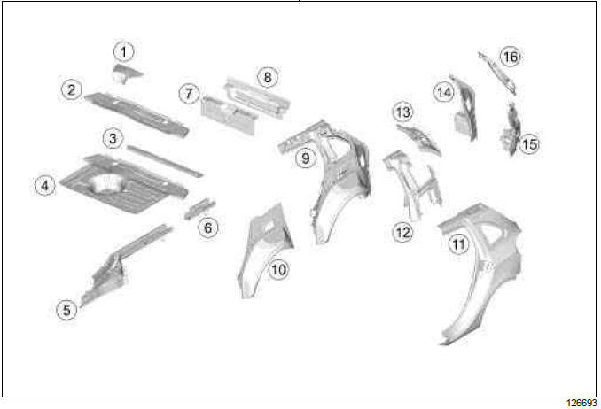
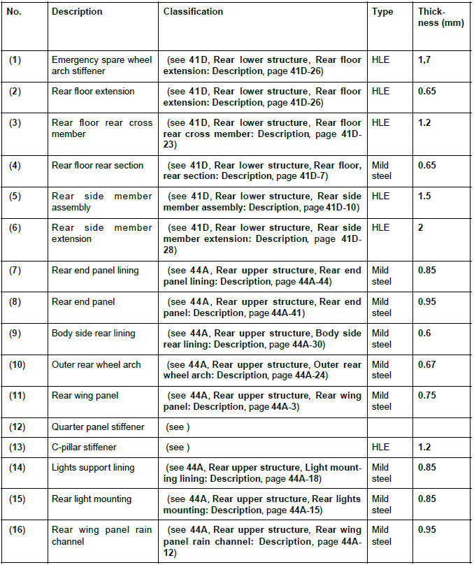
Vehicle structure, rear section: Description
REAR STRUCTURE
B85
C85 or S85, and EQUIPMENT LEVEL EA1 or EQUIPMENT LEVEL EA2 or EQUIPMENT LEVEL EA3 or EQUIPMENT LEVEL EA4 or EQUIPMENT LEVEL EA5
C85, and EQUIPMENT LEVEL SPORT
K85
READ NEXT:
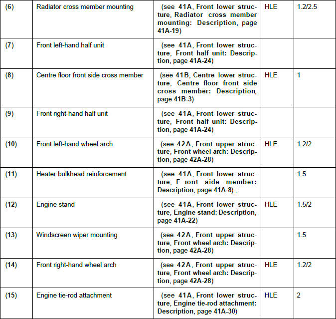
 Structural components to be positioned on the repair bench: Description
I - PARTS REQUIRING THE USE OF A BODY JIG
BENCH
Radiator cross member support
Centre floor front side cross member
Front side member closure panel
Front side member
Engine stand
Front half-uni
Front end lower cross member: General description
WARNING
The information contained in the following
describes the general repair procedure for all vehicles
having the same design for this part.
Before reading this general information, check that
th
SEE MORE:
Driving
The Renault Clio IV (2014-2019) offers a satisfying driving experience with its nimble handling and responsive performance. Its compact size and maneuverability make it well-suited for urban driving and tight parking spaces. The precise steering and suspension tuning provide a balanced and confident
Your comfort
The Renault Clio IV (2014-2019) is designed with your comfort in mind. It features a well-crafted interior with quality materials and thoughtful ergonomics. The seats offer excellent support and adjustability, providing a comfortable driving experience. The cabin is designed to minimize noise and vi
