Renault Clio: Front end lower cross member: General description
WARNING
The information contained in the following describes the general repair procedure for all vehicles having the same design for this part.
Before reading this general information, check that there are no special notes associated with this vehicle.
These special notes are specified if necessary in other parts of the sub-section dealing with the component.
Note: For a detailed description of a particular connection, see MR 400, 40A, General Information.
DESIGN OF THE STRUCTURAL COMPONENT
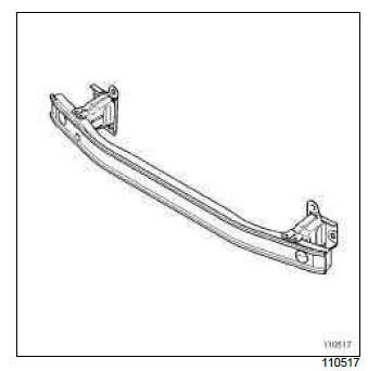
A special feature of this part is that it is bolted to the ends of the front side members via the radiator cross member mounting support.
Front impact cross member: Removal - Refitting
I - REMOVAL
1 - REMOVAL PREPARATION OPERATION
- Remove the front bumper (see Front bumper: Removal - Refitting).
- Remove the headlights (see ) (see Xenon headlight: Removal - Refitting).
2 - OPERATION FOR REMOVAL OF PART CONCERNED
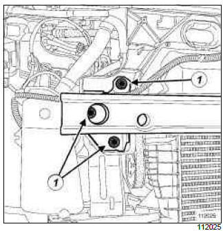
- Remove side mounting bolts (1) (three on either side).
II - REFITTING
1 - REFITTING OPERATION FOR PART CONCERNED
- Refit the side mounting bolts.
WARNING
The cross member contributes to the structural rigidity of the engine compartment. For this reason, the tightening torque must be observed following any operation.
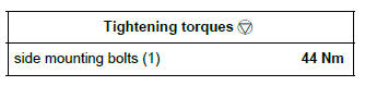
- Torque tighten the side mounting bolts (1) (44 Nm).
2 - FINAL OPERATION
- Refit the headlights (see ) (see Xenon headlight: Removal - Refitting).
- Refit the front bumper (see Front bumper: Removal - Refitting).
READ NEXT:
 Radiator mounting cross member: General description
Note:
The information contained in the following
describes the general repair procedure for all vehicles
having the same design for this part.
Before reading this general information, check that
ther
Front side member: General description
IMPORTANT
Use a repair bench to ensure the positioning of the
points and the geometry of the axle assemblies.
Note:
The information contained in the following
describes the general repair procedure fo
Front side member, centre section: General description
IMPORTANT
Use a repair bench to ensure the positioning of the
points and the geometry of the axle assemblies.
Note:
The information contained in the following
describes the general repair procedure fo
SEE MORE:
Driving
The Renault Clio IV (2014-2019) offers a satisfying driving experience with its nimble handling and responsive performance. Its compact size and maneuverability make it well-suited for urban driving and tight parking spaces. The precise steering and suspension tuning provide a balanced and confident
Your comfort
The Renault Clio IV (2014-2019) is designed with your comfort in mind. It features a well-crafted interior with quality materials and thoughtful ergonomics. The seats offer excellent support and adjustability, providing a comfortable driving experience. The cabin is designed to minimize noise and vi
