Renault Clio: Complete rear axle system: Removal - Refitting
EQUIPMENT LEVEL E3 LEISURE or EQUIPMENT LEVEL EA1 or EQUIPMENT LEVEL EA2 or EQUIPMENT LEVEL EA3 or EQUIPMENT LEVEL EA4 or EQUIPMENT LEVEL EA5 or EQUIPMENT LEVEL EAG
WARNING
Never use the rear axle as support for a lifting system.
REMOVAL
I - REMOVAL PREPARATION OPERATION
- Position the vehicle on a two-post lift (see Vehicle: Towing and lifting) (MR 392, 02A, Lifting equipment).
- Release the parking brake.
- Fit the pedal press to the brake pedal to limit the outflow of brake fluid.
- Remove the rear wheels (see 35A, Wheels and tyres, Wheel: Removal - Refitting, 35A-1).
II - OPERATION FOR REMOVAL OF PART CONCERNED
DRUM BRAKE
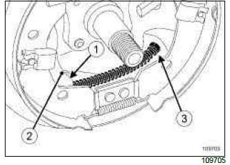
- Remove the drums (see 33A, Rear axle components, Rear brake drum: Removal - Refitting, 33A-19).
- Remove the parking brake cable (1) from the lever (2) using pliers and a screwdriver.
- Unclip the parking brake cable sheath (3) from the drum back-plate.
- Unclip the wheel speed sensors from the back-plate.
- Unclip the wheel speed sensors from the rear axle.
DISC BRAKE
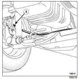
- Remove the parking brake cables (4) at the brake callipers.
- Unclip the wheel speed sensors.
- Unclip the wheel speed sensors from the rear axle.
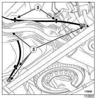
- Unclip the parking brake cables from their guides (5)
- Note the parking brake cable routing for refitting.
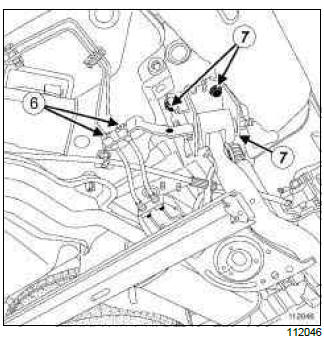
- Unscrew the unions (6) connecting the rigid pipes and the brake hoses.
- Loosen the rear axle bearing bolts (7).
- Remove the springs (see 33A, Rear axle components, Rear suspension spring: Removal - Refitting, 33A-27).
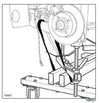
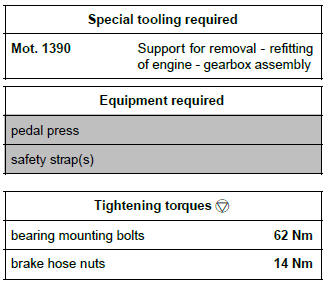
- Fit the (Mot. 1390) under the rear axle.
- Position the pads of the (Mot. 1390) in contact with the rear axle.
- Put a safety strap(s) around the rear axle.
- Remove the rear axle bearing bolts.
- Raise the vehicle.
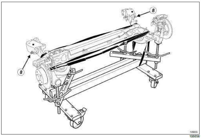
- Remove the rear axle components (do not undo the rubber bush bolts (8) ).
REFITTING
I - REMOVAL PREPARATION OPERATION
- Refit the rear axle equipment.
- Strap the rear axle onto the (Mot. 1390).
- Degrease the surfaces of the body which are in contact with the rear axle bearing using surface cleaner.
- Position the rear axle under the vehicle.
II - REFITTING OPERATION FOR PART CONCERNED
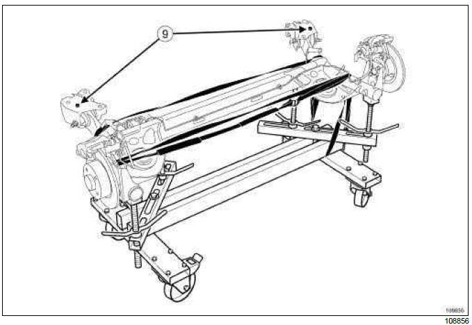
- Lower the lift.
- Position the bearing centring devices (9) opposite the centring holes.
- Refit the mountings, starting with the left-hand bearing.
- Raise the lift.
- Remove the safety strap(s).
- Remove the (Mot. 1390).
- Insert the brake pipes into their housing.
- Screw on the brake hose nuts.
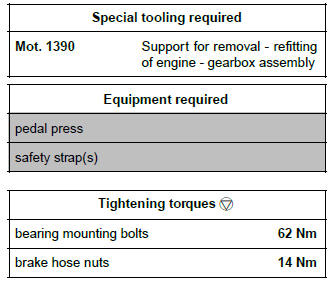
- Tighten to torque:
- the bearing mounting bolts (62 Nm),
- the brake hose nuts (14 Nm).
- Refit the springs (see 33A, Rear axle components, Rear suspension spring: Removal - Refitting, 33A-27).
- Clip on and connect the wheel speed sensor connectors.
- Refit the parking brake cables in their guides and on the calliper (or backplate).
- Check that the parking brake cable stops are properly inserted in their housing.
DRUM BRAKE
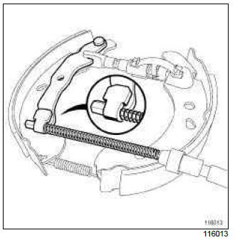
- Check that the parking brake cable is correctly positioned on the parking brake lever.
- Adjust the parking brake cables (see 37A, Mechanical component controls, Parking brake lever: Adjustment, 37A-90).
III - FINAL OPERATION
- Refit the rear wheels (see 35A, Wheels and tyres, Wheel: Removal - Refitting, 35A-1).
- Bleed the brake circuit (see 30A, General information, Braking circuit: Bleed, 30A-4).
EQUIPMENT LEVEL EAC or EQUIPMENT LEVEL SPORT
WARNING
Never use the rear axle as support for a lifting system.
REMOVAL
I - REMOVAL PREPARATION OPERATION
- Position the vehicle on a two-post lift (see Vehicle: Towing and lifting) (MR 392, 02A, Lifting equipment).
- Release the parking brake.
- Fit the pedal press to the brake pedal to limit the outflow of brake fluid.
- Remove the rear wheels (see 35A, Wheels and tyres, Wheel: Removal - Refitting, 35A-1).
II - OPERATION FOR REMOVAL OF PART CONCERNED
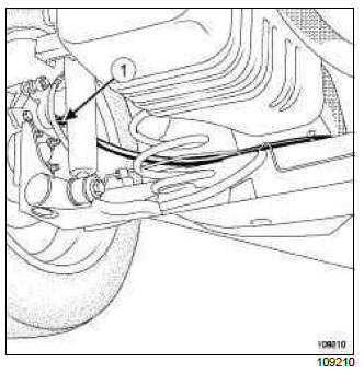
- Remove the parking brake cables (1) at the brake callipers.
- Unclip the wheel speed sensors.
- Unfasten the wheel speed sensors from the rear axle.
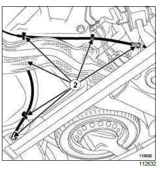
- Unfasten the parking brake cables from their guides (2).
- Note the parking brake cable routing for refitting.
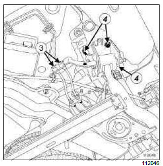
- Unscrew the unions (3) connecting the rigid pipes and the brake hoses.
- Loosen the rear axle bearing bolts (4).
- Remove the suspension springs (see 33A, Rear axle components, Rear suspension spring: Removal - Refitting, 33A-27).
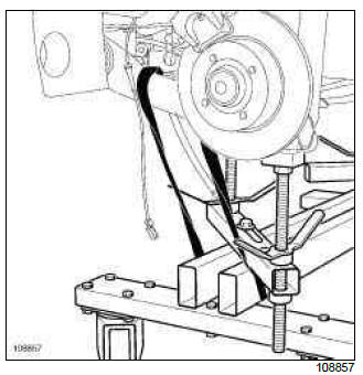
- Fit the (Mot. 1390) under the rear axle.
- Position the pads of the (Mot. 1390) in contact with the rear axle.
- Put a safety strap(s) around the rear axle.
- Remove the rear axle bearing bolts.
- Raise the vehicle.
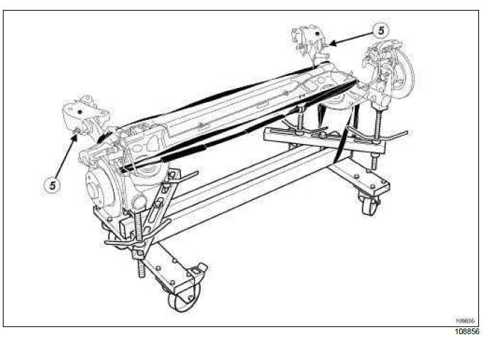
- Remove the rear axle components (do not undo the rubber bush bolts (5) ).
REFITTING
I - REFITTING PREPARATIONS OPERATION
- Refit the rear axle equipment.
- Strap the rear axle onto the (Mot. 1390).
- Position the rear axle under the vehicle.
II - REFITTING OPERATION FOR PART CONCERNED
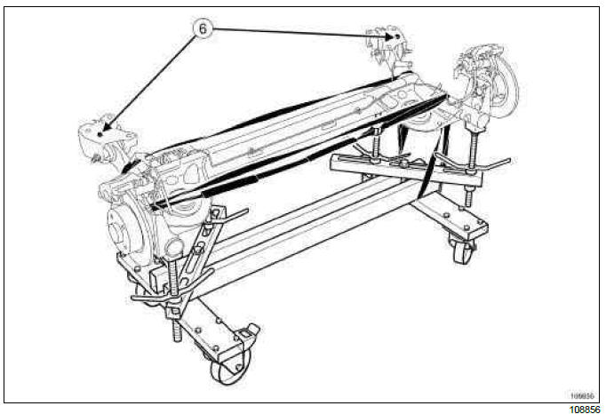
- Lower the lift.
- Position the bearing centring devices (6) opposite the centring holes.
- Refit the mountings, starting with the left-hand bearing.
- Raise the lift.
- Remove the safety strap(s).
- Remove the (Mot. 1390).
- Insert the brake pipes into their housing.
- Screw on the brake hose nuts.
- Torque tighten:
- the bearing mounting bolts (62 Nm),
- the brake hose nuts (14 Nm).
- Refit the suspension springs (see 33A, Rear axle components, Rear suspension spring: Removal - Refitting, 33A-27).
- Clip on and connect the wheel speed sensor connectors.
- Refit the parking brake cables into the guides and onto the calliper.
- Check that the parking brake cable stops are properly inserted in their housing.
- Adjust the parking brake cables (see 37A, Mechanical component controls, Parking brake lever: Adjustment, 37A-90)
III - FINAL OPERATION.
- Refit the rear wheels (see 35A, Wheels and tyres, Wheel: Removal - Refitting, 35A-1).
- Bleed the brake circuit (see 30A, General information, Braking circuit: Bleed, 30A-4).

