Renault Clio: Driveshaft: Precautions for the repair
DP0 or JH3 or JR5 or TL4
WARNING
A gearbox oil leak at the driveshaft may destroy it.
WARNING
Always replace seals whenever the driveshaft is removed.
WARNING
Grease the base of the bearing using BR 2 + grease to prevent the bearing from sticking.
Make sure that the O-ring is correctly positioned in the base of the relay bearing, if the bearing has one.
WARNING
Always replace the O-ring, if fitted to the bearing.
WARNING
Always replace the relay bearing support plate.
WARNING
Always replace the left-hand driveshaft locking spring ring, if the driveshaft has one.
WARNING
In order to prevent irreversible damage to the front hub bearing:
- Do not loosen or tighten the driveshaft nut when the wheels are on the ground.
- Do not place the vehicle with its wheels on the ground when the driveshaft has been loosened or removed.
Front left-hand driveshaft: Removal - Refitting
DP0 or JH3 or JR5 - K4M or K9K or M4R, and TL4
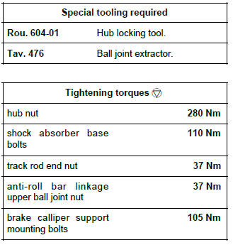
REMOVAL
I - REMOVAL PREPARATION OPERATION
- Position the vehicle on a two-post lift (see Vehicle: Towing and lifting) (MR 392, 02A, Lifting equipment).
- Remove the engine undertray.
- Remove the front right-hand wheel (see Wheel: Removal - Refitting) (MR 392, 35A, Wheels and tyres).
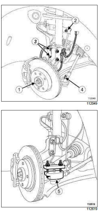
- Unclip the left-hand wheel speed sensor.
- Remove:
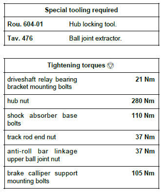
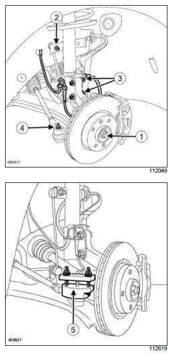
- the hub nut (1), using the (Rou. 604-01),
- the left-hand steering ball joint (4), using the (Tav. 476) at (5),
- the left-hand upper ball joint of the anti-roll bar linkage (2),
- the left-hand brake calliper support mounting bolts (see Front brake calliper mounting: Removal - Refitting) (MR 392, 31A, Front axle components),
- the left-hand shock absorber lower mounting bolts (3).
- Attach the brake calliper to the shock absorber spring.
II - REMOVAL OF PART CONCERNED
- Pivot the stub axle carrier to separate the driveshaft from the stub axle carrier.
- Remove the driveshaft from the gearbox.
REFITTING
I - REFITTING PART CONCERNED
- Insert the driveshaft splines into the differential grooves.
- Insert the drive shaft splines in the hub grooves.
- Fit the left-hand shock absorber lower mounting bolts.
II - FINAL OPERATION
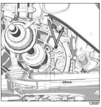
Note: If equipped with the 5thinjector.
After carrying out the operation, check that the dimension between the driveshaft and the hose for the 5thinjector is at least 25mm.
To avoid damaging the hose.
- Fit:
- the left-hand track rod end,
- the left-hand upper ball joint of the anti-roll bar linkage,
- the left-hand brake calliper support mounting bolts (see Front brake calliper mounting: Removal - Refitting) (MR 392, 31A, Front axle components).
- Tighten to torque:
- the hub nut (280 Nm), using the (Rou. 604-01),
- the shock absorber base bolts (110 Nm),
- the track rod end nut (37 Nm),
- the anti-roll bar linkage upper ball joint nut (37 Nm),
- the brake calliper support mounting bolts (105 Nm) (see Front brake calliper mounting: Removal - Refitting) (MR 392, 31A, Front axle components).
- Refasten the clips on the wheel speed sensor.
- Refit the engine undertray.
- Refit the front left-hand wheel (see Wheel: Removal - Refitting) (MR 392, 35A, Wheels and tyres).
F4R, and TL4
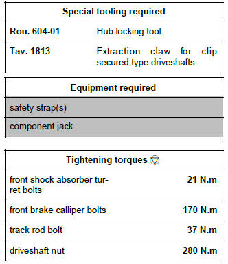
REMOVAL
I - REMOVAL PREPARATION OPERATION
- Position the vehicle on a two-post lift (see Vehicle: Towing and lifting) (02A, Lifting equipment).
- Disconnect the battery (see Battery: Removal - Refitting) (80A, Battery).
- Remove:
- the engine undertray bolts,
- the engine undertray,
- the front left-hand wheel (see Wheel: Removal - Refitting) (35A, Wheels and tyres).
- Drain the gearbox oil (see 21A, Manual gearbox, Manual gearbox oils: Draining - Filling, 21A-3).
II - OPERATION FOR REMOVAL OF PART CONCERNED
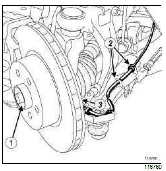
- Remove the nut from the front left-hand driveshaft (1) using the tool (Rou. 604-01).
- Unclip the ABS sensor wiring harness (2).
- Remove the ABS sensor bolt (3).
- Move the ABS sensor to one side.
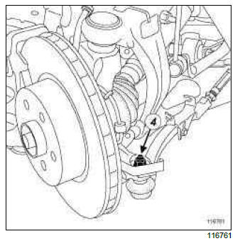
- Remove:
- the track rod nut (4),
- the track rod.
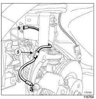
- Remove the bolt (5) from the clip on the front brake hose.
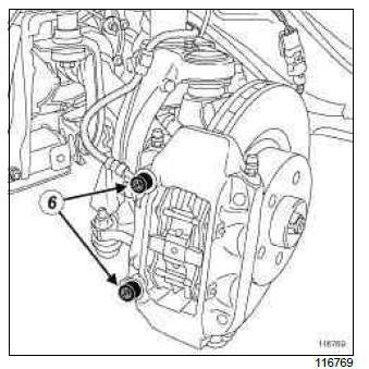
- Remove the front brake calliper bolts (6).
- Move the front brake calliper away and attach it using a safety strap(s) to the spring of the front shock absorber.
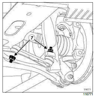
- Remove the linkage nuts (7).
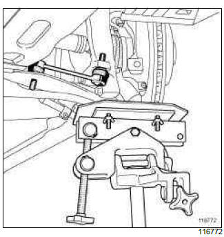
- Fit a component jack to compress the front suspension.
- Remove the linkage.
- Remove the component jack.
- Remove the scuttle panel grille (see Scuttle panel grille: Removal - Refitting) (56A, Exterior equipment).
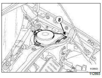
- Remove:
- the nut (8) from the cover of the front shock absorber turret,
- the cover of the front shock absorber turret.
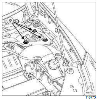
- Loosen the bolts (9) on the front shock absorber turret.
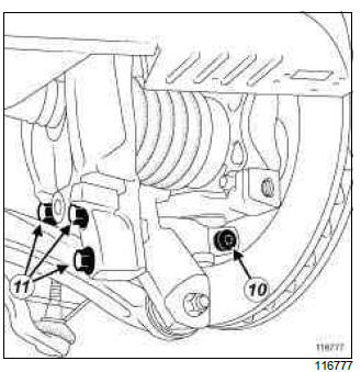
- Remove:
- the hub carrier lower shaft bolt (10),
- the bolts (11) from the pivot support.
- Separate the spring - shock absorber - pivot assembly.
- Remove:
- the front left-hand driveshaft from the front left-hand wheel hub,
- the front left-hand driveshaft from the gearbox.
- Remove the front left-hand driveshaft using the tool (Tav. 1813) and.
REFITTING
I - REFITTING PREPARATION OPERATION
- Remove the left-hand side differential output seal (see 21A, Manual gearbox, Differential output seal: Removal - Refitting, 21A-46).
- Refit a new differential output seal on the left-hand side (see 21A, Manual gearbox, Differential output seal: Removal - Refitting, 21A-46).
II - REFITTING OPERATION FOR PART CONCERNED
- Fit the front left-hand driveshaft by inserting it into the gearbox then into the front wheel hub.
- Refit:
- the bolts of the pivot support,
- the hub carrier lower shaft bolt.
- Torque tighten the front shock absorber turret bolts (21 N.m).
- Fit a component jack to compress the front suspension.
- Refit the linkage.
- Remove the component jack.
- Refit the linkage nuts.
- Fit the front brake calliper.
- Torque tighten the front brake calliper bolts (170 N.m).
- Refit the bolt of the clip on the front brake calliper hose.
- Position the track rod.
- Refit the track rod nut.
- Torque tighten the track rod bolt (37 N.m).
- Refit:
- the ABS sensor,
- the ABS sensor bolt.
- Clip the ABS sensor wiring harness.
- Refit the driveshaft nut using the (Rou. 604-01).
- Torque tighten the driveshaft nut (280 N.m).
III - FINAL OPERATION
- Refit:
- the cover of the front shock absorber turret,
- the nut for the cover of the front shock absorber turret,
- the scuttle panel grille (see Scuttle panel grille: Removal - Refitting) (56A, Exterior equipment),
- the front left-hand wheel (see Wheel: Removal - Refitting) (35A, Wheels and tyres).
- Top up the gearbox (see 21A, Manual gearbox, Manual gearbox oils: Draining - Filling, 21A-3).
- Refit the engine undertray.
- Connect the battery (see Battery: Removal - Refitting) (80A, Battery).
Front right-hand driveshaft: Removal - Refitting
JH3 or JR5 - K4M or K9K or M4R, and TL4
REMOVAL
I - REMOVAL PREPARATION OPERATION
- Position the vehicle on a two-post lift (see Vehicle: Towing and lifting) (MR 392, 02A, Lifting equipment).
- Remove the engine undertray.
- Drain the gearbox (see 21A, Manual gearbox, Manual gearbox oils: Draining - Filling, 21A-3).
- Remove the front right-hand wheel (see Wheel: Removal - Refitting) (MR392, 35A, Wheels and tyres).
- Unclip the right-hand wheel speed sensor.
- Remove:
- the hub nut (1) using the (Rou. 604-01),
- the anti-roll bar linkage right-hand upper ball joint (2),
- the right-hand track rod end (4), using the (Tav.476) at (5),
- the right-hand brake calliper support mounting bolts (see Front brake calliper mounting: Removal - Refitting) (MR 392, 31A, Front axle components),
- the right-hand shock absorber lower mounting bolts (3).
- Attach the brake calliper to the shock absorber spring.
D4F, and 740 or 742, and JH3
- Remove:
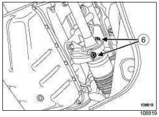
- the driveshaft relay bearing bracket mounting bolts (6),
- the driveshaft relay bearing bracket.
K4J, and 780, and JH3 - K4M, and 800, and JH3 - K9K, and 768, and JH3 - K9K, and 766, and JR5
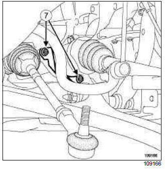
- Remove:
- the driveshaft relay bearing bracket mounting bolts (7),
- the driveshaft relay bearing bracket.
K9K, and 764, and TL4
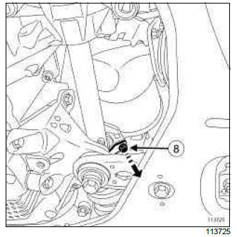
- Remove the driveshaft relay bearing bracket mounting bolt (8).
- Pivot the driveshaft relay bearing bracket.
II - REMOVAL OF PART CONCERNED
- Pivot the stub axle carrier to separate the driveshaft from the stub axle carrier.
- Remove the driveshaft from the gearbox.
REFITTING
I - REFITTING PREPARATION OPERATION
- Check the condition of the lip seal mating face on the driveshaft.
WARNING
Do not refit a driveshaft if the lip seal mating face is damaged.
- Replace the differential output lip seal (see 21A, Manual gearbox, Differential output seal: Removal - Refitting, 21A-46).
II - REFITTING PART CONCERNED
- Engage the driveshaft splines with the differential splines as straight as possible, so as to not damage the seal.
- Engage the driveshaft splines with the hub splines.
III - FINAL OPERATION.
- Tighten to torque:
- the driveshaft relay bearing bracket mounting bolts (21 Nm),
- the hub nut (280 Nm), using the (Rou. 604-01),
- the shock absorber base bolts (110 Nm),
- the track rod end nut (37 Nm),
- the anti-roll bar linkage upper ball joint nut (37 Nm),
- the brake calliper support mounting bolts (105 Nm) (see Front brake calliper mounting: Removal - Refitting) (MR 392, 31A, Front axle components).
- Refasten the clips on the wheel speed sensor.
- Top up the gearbox (see 21A, Manual gearbox, Manual gearbox oils: Draining - Filling, 21A-3).
- Refit the engine undertray.
- Refit the front right-hand wheel (see Wheel: Removal - Refitting) (MR 392, 35A, Wheels and tyres).
DP0
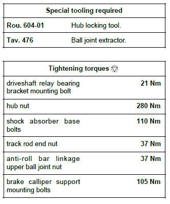
REFITTING
I - REMOVAL PREPARATION OPERATION
- Position the vehicle on a two-post lift (see Vehicle: Towing and lifting) (MR 392, 02A, Lifting equipment).
- Remove the engine undertray.
- Remove the front right-hand wheel (see Wheel: Removal - Refitting) (MR 392, 35A, Wheels and tyres).
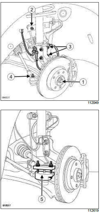
- Unclip the right-hand wheel speed sensor.
- Remove:
- the hub nut (1) using the (Rou. 604-01),
- the anti-roll bar linkage right-hand upper ball joint (2),
- the right-hand track rod end (4), using the (Tav.476) at (5),
- the right-hand brake calliper support mounting bolts (see Front brake calliper mounting: Removal - Refitting) (MR 392, 31A, Front axle components),
- the right-hand shock absorber lower mounting bolts (3).
- Attach the brake calliper to the shock absorber spring.
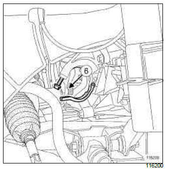
- Remove the driveshaft relay bearing bracket mounting bolt (6).
II - REMOVAL OF PART CONCERNED
- Pivot the stub axle carrier to separate the driveshaft from the stub axle carrier.
- Remove the driveshaft from the gearbox.
REMOVAL
I - REFITTING PART CONCERNED
- Insert the driveshaft splines into the differential grooves.
- Insert the drive shaft splines in the hub grooves.
- Fit:
- the right-hand shock absorber lower mounting bolts,
- the driveshaft relay bearing bracket.
- Refit the driveshaft relay bearing bracket mounting bolt (6).
II - FINAL OPERATION
- Fit:
- the right-hand track rod end,
- the anti-roll bar linkage right-hand upper ball joint,
- the right-hand brake calliper support mounting bolts (see Front brake calliper mounting: Removal - Refitting) (MR 392, 31A, Front axle components).
- Torque tighten:
- the driveshaft relay bearing bracket mounting bolt (21 Nm),
- the hub nut (280 Nm), using the (Rou. 604-01),
- the shock absorber base bolts (110 Nm),
- the track rod end nut (37 Nm),
- the anti-roll bar linkage upper ball joint nut (37 Nm),
- the brake calliper support mounting bolts (105 Nm) (see Front brake calliper mounting: Removal - Refitting) (MR 392, 31A, Front axle components).
- Refasten the clips on the wheel speed sensor.
- Refit the engine undertray.
- Refit the front right-hand wheel (see Wheel: Removal - Refitting) (MR 392, 35A, Wheels and tyres).
F4R, and TL4
REMOVAL
I - REMOVAL PREPARATION OPERATION
- Position the vehicle on a two-post lift (see Vehicle: Towing and lifting) (MR 392, 02A, Lifting equipment).
- Disconnect the battery (see Battery: Removal - Refitting) (MR 392, 80A, Battery).
- Remove:
- the engine undertray,
- the front right-hand wheel (see Wheel: Removal - Refitting) (MR 392, 35A, Wheels and tyres).
- Drain the gearbox oil (see 21A, Manual gearbox, Manual gearbox oils: Draining - Filling, 21A-3).
II - OPERATION FOR REMOVAL OF PART CONCERNED
- Remove the driveshaft nut using the (Rou. 604-01).
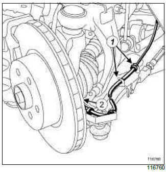
- Unclip the ABS sensor wiring harness (1).
- Remove the ABS sensor mounting bolt (2).
- Move the ABS sensor to one side.
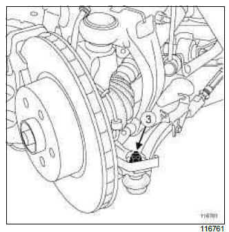
- Remove the track rod mounting nut (3).
- Remove the track rod.
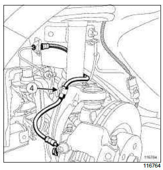
- Remove the calliper hose mounting bolt (4).
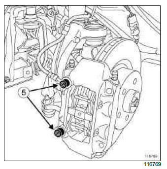
- Remove the brake calliper mounting bolts (5).
- Remove the brake calliper and strap it up (see Front brake calliper: Removal - Refitting) (MR 392, 31A, Front axle components).
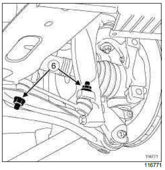
- Remove the linkage nuts (6).
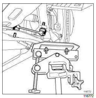
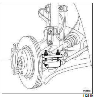
- Fit a component jack to compress the suspension.
- Remove the linkage.
- Remove the component jack.
- Remove the scuttle panel grille (see Scuttle panel grille: Removal - Refitting) (MR 393, 55A, Exterior protection).
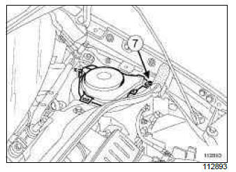
- Remove:
- the turret cover mounting nut (7),
- the turret cover.
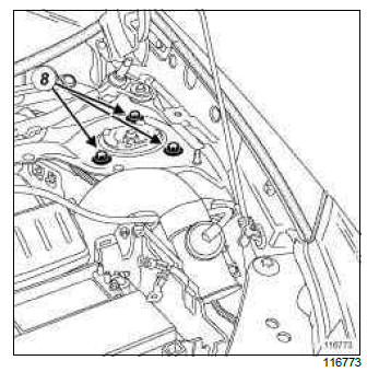
- Loosen the turret mounting bolts (8).
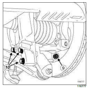
- Remove:
- the hub carrier lower axis locking bolt (9),
- the mounting bolts (10) from the pivot mounting.
- Remove the "spring - shock absorber - pivot" assembly.
- Extract the hub driveshaft.
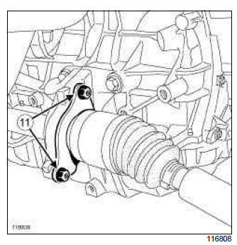
- Remove the right-hand driveshaft relay bearing support plate mounting bolts (11).
- Extract the driveshaft from the gearbox.
- Remove the right-hand driveshaft.
REFITTING
I - REFITTING PREPARATIONS OPERATION
- Replace the differential output seal (see 21A, Manual gearbox, Differential output seal: Removal - Refitting, 21A-46).
WARNING
Always replace the differential output lip seal with a new one whenever the driveshafts are removed.
II - REFITTING OPERATION FOR PART CONCERNED
- Fit the driveshaft by inserting it into the gearbox and then the hub carrier.
- Refit:
- the driveshaft relay bearing support plate,
- the driveshaft relay bearing support plate mounting bolts.
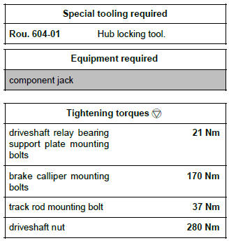
- Torque tighten the driveshaft relay bearing support plate mounting bolts (21 Nm)
- Refit:
- the pivot mounting bolts,
- the hub carrier lower axis locking bolt.
- Fit a component jack to compress the suspension.
- Refit the linkage.
- Remove the component jack.
- Refit the linkage mounting bolts.
- Refit the brake calliper mounting bolts.
- Tighten to torque the brake calliper mounting bolts (170 Nm).
- Refit the calliper hose mounting bolt.
- Position the track rod.
- Refit the track rod mounting nut.
- Tighten to torque the track rod mounting bolt (37 Nm).
- Refit the ABS sensor.
- Clip the ABS sensor wiring harness.
- Refit the driveshaft nut using the (Rou. 604-01).
- Tighten to torque the driveshaft nut (280 Nm)
III - FINAL OPERATION.
- Refit:
- the turret cover,
- the turret cover mounting nut,
- the scuttle panel grille (see Scuttle panel grille: Removal - Refitting) (MR 393, 55A, Exterior protection),
- the front right-hand wheel (see Wheel: Removal - Refitting) (MR 392, 35A, Wheels and tyres).
- Top up the gearbox (see 21A, Manual gearbox, Manual gearbox oils: Draining - Filling, 21A-3).
- Refit the engine undertray.
- Connect the battery (see Battery: Removal - Refitting) (MR 392, 80A, Battery).

