Renault Clio: Headlight: Adjustment
DOCUMENTATION PHASE 1
ADJUSTMENT
I - PREPARATION OPERATION FOR CHECK
- Place the vehicle in a working area equipped with a two-post lift.
Note: Check that the lift is on flat, horizontal ground.
- Do not apply the parking brake.
- Check and inflate the tyres to the recommended pressure (see Tyre pressure: Identification) (35A, Wheels and tyres).
- Open the bonnet.
- Check:
- that the luggage compartment is empty,
- that the headlights are clean.
Note: Do not get into the vehicle throughout the operation.
WITHOUT DISCHARGE LAMPS
- Position the headlight beam remote adjustment control on 0.
- Switch on the dipped headlights.
II - TEST OPERATION
WARNING
Consult the device's operating manual to avoid incorrect use.
WITHOUT DISCHARGE LAMPS
- Place the headlight adjustment and checking tool adjusted to -1% in front of the vehicle.
DISCHARGE LAMPS
- Place the headlight adjustment and checking tool adjusted to -1.3% in front of the vehicle.
- Using the headlight adjustment and checking tool, check the headlight beam adjustment.
III - ADJUSTMENT OPERATION
1 - Left-hand headlight
- Raise the vehicle (see Vehicle: Towing and lifting) (02A, Lifting equipment).
- Remove:
- the front left-hand wheel (see Wheel: Removal - Refitting) (35A, Wheels and tyres),
- the front section of the front left-hand wheel arch liner (see Front wheel arch liner: Removal - Refitting) (55A, Exterior protection).
- Refit the front left-hand wheel (see Wheel: Removal - Refitting) (35A, Wheels and tyres).
- Lower the vehicle.
- Position the vehicle back on the ground.
- Compress the suspension.
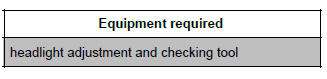
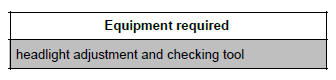
- Using the headlight adjustment and checking
tool :
- perform lateral adjustment of the headlight using the screw (2),
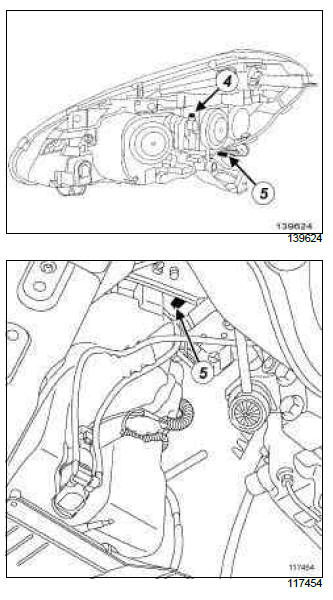
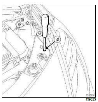
- perform the beam adjustment using the screw located above the headlight (1).
JAPAN SPECIAL FEATURES
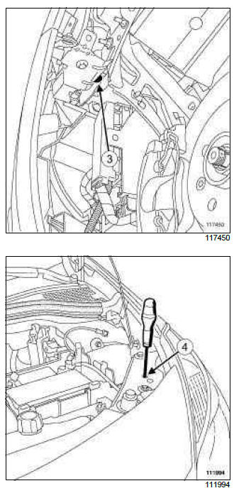
- Using the headlight adjustment and checking
tool :
- perform lateral adjustment of the headlight using the screw (3),
- perform the beam adjustment using the screw located above the headlight (4).
2 - Right-hand headlight
- Raise the vehicle (see Vehicle: Towing and lifting) (02A, Lifting equipment).
- Remove:
- the front right-hand wheel (see Wheel: Removal - Refitting) (35A, Wheels and tyres),
- the front section of the front right-hand wheel arch liner (see Front wheel arch liner: Removal - Refitting) (55A, Exterior protection).
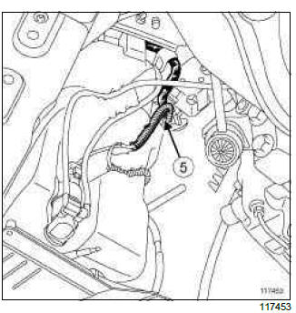
- Move aside the washer fluid pump electrical wiring (5) to access the lateral adjustment screw.
- Refit the front right-hand wheel (see Wheel: Removal - Refitting) (35A, Wheels and tyres).
- Lower the vehicle.
- Position the vehicle back on the ground.
- Compress the suspension.

- Using the headlight adjustment and checking
tool :
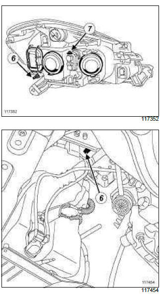
- perform lateral adjustment of the headlight using the screw (6),
- perform the beam adjustment using the screw located above the headlight (7).
JAPAN SPECIAL FEATURES
-
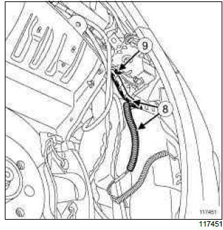
Move aside the washer fluid pump electrical wiring (8) to access the adjustment screw.
- Using the headlight adjustment and checking
tool :
- perform lateral adjustment of the headlight using the screw (9),
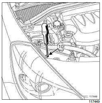
- perform the beam adjustment using the screw located above the headlight (10).
IV - FINAL OPERATION
- Raise the vehicle.
- Remove the front wheels (see Wheel: Removal - Refitting) (35A, Wheels and tyres).
- Refit:
- the front section of the front wheel arch liners (see Front wheel arch liner: Removal - Refitting) (55A, Exterior protection),
- the front wheels (see Wheel: Removal - Refitting) (35A, Wheels and tyres).
- Lower the vehicle.
- Close the bonnet.
DOCUMENTATION PHASE 2
ADJUSTMENT
I - PREPARATION OPERATION FOR CHECK
Place the vehicle in a working area equipped with a two-post lift.
Note: Check that the lift is on flat, horizontal ground.
- Do not apply the parking brake.
- Check and inflate the tyres to the recommended pressure (see Tyre pressure: Identification) (35A, Wheels and tyres).
- Open the bonnet.
- Check:
- that the luggage compartment is empty,
- that the headlights are clean.
Note: Do not get into the vehicle throughout the operation.
- Position the headlight beam remote adjustment control on 0.
- Switch on the dipped headlights.
II - TEST OPERATION
WARNING
Consult the device's operating manual to avoid incorrect use.
- Place the headlight adjustment and checking tool adjusted to -1% in front of the vehicle.
- Using the headlight adjustment and checking tool, check the headlight beam adjustment.
III - ADJUSTMENT OPERATION
- Raise the vehicle (see Vehicle: Towing and lifting) (02A, Lifting equipment).
- Remove:
- the front wheels (see Wheel: Removal - Refitting) (35A, Wheels and tyres),
- the front section of the front wheel arch liners (see Front wheel arch liner: Removal - Refitting) (55A, Exterior protection).
- Refit the front wheels (see Wheel: Removal - Refitting) (35A, Wheels and tyres).
- Lower the vehicle.
- Position the vehicle back on the ground.
- Compress the suspension.
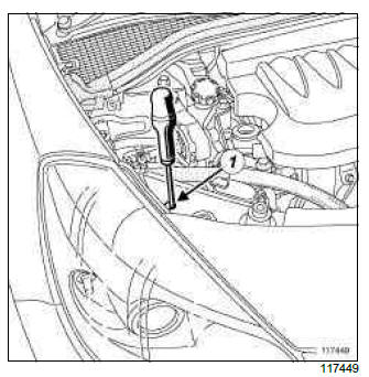
1 - Left-hand headlight
- Using the headlight adjustment and checking
tool :
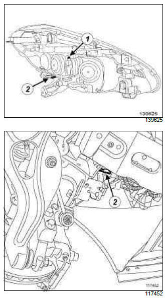
- perform lateral adjustment of the headlight using the screw (1),
- perform the beam adjustment using the screw located above the headlight (2).
2 - Right-hand headlight
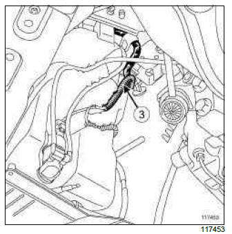
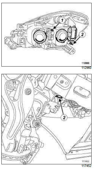
-
Move aside the washer fluid pump wiring (3) to access the lateral adjustment screw.
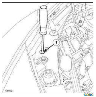
- Using the headlight adjustment and checking
tool :
- perform lateral adjustment of the headlight using the screw (5),
- perform the beam adjustment using the screw located above the headlight (4).
IV - FINAL OPERATION
- Raise the vehicle.
- Remove the front wheels (see Wheel: Removal - Refitting) (35A, Wheels and tyres).
- Refit:
- the front section of the front wheel arch liners (see Front wheel arch liner: Removal - Refitting) (55A, Exterior protection),
- the front wheels (see Wheel: Removal - Refitting) (35A, Wheels and tyres).
- Lower the vehicle.
READ NEXT:
 Headlight bulb: Removal - Refitting
DOCUMENTATION PHASE 1
REMOVAL
DISCHARGE LAMPS
IMPORTANT
To prevent eye injuries:
do not look at a xenon bulb when lit (voltage
when lit 20000 V),
do not light a bulb which has not been fitted into
Remote headlight beam adjustment actuator: Removal - Refitting
DOCUMENTATION PHASE 1
DISCHARGE LAMPS
IMPORTANT
To prevent burns, wait until the " computers -
power unit " assemblies are cold before removal.
IMPORTANT
To prevent eye injuries:
do not look at a xe
Headlight beam adjustment front sensor: Removal - Refitting
DISCHARGE LAMPS
REMOVAL
I - REMOVAL PREPARATION OPERATION
Position the vehicle on a lift (see Vehicle: Towing
and lifting) (MR 392, 02A, Lifting equipment).
Remove:
the front wheels (see Wheel:
SEE MORE:
Driving
The Renault Clio IV (2014-2019) offers a satisfying driving experience with its nimble handling and responsive performance. Its compact size and maneuverability make it well-suited for urban driving and tight parking spaces. The precise steering and suspension tuning provide a balanced and confident
Your comfort
The Renault Clio IV (2014-2019) is designed with your comfort in mind. It features a well-crafted interior with quality materials and thoughtful ergonomics. The seats offer excellent support and adjustability, providing a comfortable driving experience. The cabin is designed to minimize noise and vi
