Renault Clio: M4R, and Right-hand Drive
Renault Clio III (2005-2013) Service Manual / Chassis / Mechanical Component Controls / Brake servo: Removal - Refitting / M4R, and Right-hand Drive
REMOVAL
I - REMOVAL PREPARATION OPERATION
- Position the vehicle on a two-post lift (see Vehicle: Towing and lifting) (MR 392, 02A, Lifting equipment).
- Disconnect the battery (see Battery: Removal - Refitting) (MR 392, 80A, Battery).
- Remove:
- the engine cover,
- the engine undertray,
- the scuttle panel grille (see Scuttle panel grille: Removal - Refitting) (MR 393, 56A, Exterior equipment),
- the scoop under the scuttle panel grille (see Scoop under the scuttle panel grille: Removal - Refitting) (MR 393, 56A, Exterior equipment),
- the non-return valve on the servo,
- the master cylinder (see 37A, Mechanical component controls, Master cylinder: Removal - Refitting, 37A-2),
- the intake distributor (see Inlet distributor: Removal - Refitting) (MR 392, 12A, Fuel mixture).
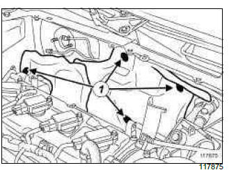
- Remove the clips (1) from the acoustic shield.
- Move aside the acoustic shield.
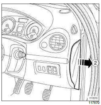
- Remove the dashboard side face (2).
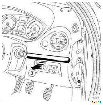
- Unclip protective strip (3).

- Remove:
- the bolts (4) from the lower cover,
- the lower cover, disconnecting the various connectors.
- the engine tie-bar (see Lower engine tie-bar: Removal - Refitting) (MR 392, 19D, Engine mounting).
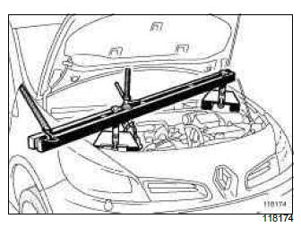
- Fit the (Mot. 1453).
- Remove the right-hand suspended mounting support (see Right-hand suspended engine mounting: Removal - Refitting) (MR 392, 19D, Engine mounting).
- Lower the engine as much as possible using the (Mot. 1453).
II - OPERATION FOR REMOVAL OF PART CONCERNED
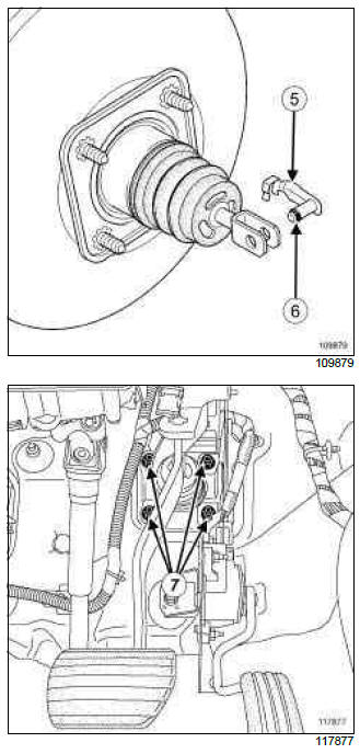
- Tilt the connecting shaft (5) upwards.
- Remove:
- the double safety connecting shaft using a flat-blade screwdriver to move the ring (6),
- the brake servo nuts (7).
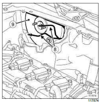
- Move aside the brake pipes (8).
- Remove the brake servo (9).
Note: To pass the servo between the bulkhead and the engine, the pushrod must be oriented towards the bottom, with the engine slightly pulled forward.
REFITTING
I - REFITTING PREPARATIONS OPERATION
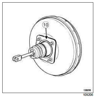
- Check that the brake servo sealing ring is in place (10).
- Replace the seal if it is damaged.
- The shaft connecting the brake servo pushrod and the brake pedal must be replaced every time it is removed.

- Before refitting, check that the dimension: (X1) = 128 mm.
II - REFITTING OPERATION FOR PART CONCERNED
- Refit:
- the brake servo,
- the brake servo nuts.
- The shaft connecting the brake servo pushrod and the brake pedal must be refitted from right to left, and from top to bottom.
- Torque tighten the brake servo nuts (21 Nm).
III - FINAL OPERATION.
- Refit:
- the bulkhead acoustic shield,
- the bulkhead acoustic shield clips,
- the right-hand suspended mounting support (see Right-hand suspended engine mounting: Removal - Refitting) (MR 392, 19D, Engine mounting).
- Remove the (Mot. 1453).
- Refit:
- the engine tie-bar (see Lower engine tie-bar: Removal - Refitting) (MR 392, 19D, Engine mounting),
- the intake distributor (see Inlet distributor: Removal - Refitting) (MR 392, 12A, Fuel mixture),
- the master cylinder (see 37A, Mechanical component controls, Master cylinder: Removal - Refitting, 37A-2),
- the non-return valve on the servo,
- the scoop under the scuttle panel grille (see Scoop under the scuttle panel grille: Removal - Refitting) (MR 393, 56A, Exterior equipment),
- the scuttle panel grille (see Scuttle panel grille: Removal - Refitting) (MR 393, 56A, Exterior equipment),
- the engine undertray,
- the engine cover.
- Bleed the brake circuit (see 30A, General information, Braking circuit: Bleed, 30A-4).
- Adjust the brake light switch (see 37A, Mechanical component controls, Brake pedal switch: Removal - Refitting, 37A-79).
- Check that the connecting shaft between the brake servo pushrod and the brake pedal is locked in place.
- Refit:
- the lower cover and connect the various connectors,
- the lower cover bolts,
- the dashboard side panel,
- the lower cover strip,
- Connect the battery (see Battery: Removal - Refitting) (MR 392, 80A, Battery).
READ NEXT:
 F4R, and Right-hand Drive
REMOVAL
I - REMOVAL PREPARATION OPERATION
Position the vehicle on a two-post lift (see Vehicle:
Towing and lifting) (MR 392, 02A, Lifting equipment).
Disconnect the battery (see Battery: Removal
D4F, and 784, and Right-hand Drive
REMOVAL
I - REMOVAL PREPARATION OPERATION
Remove the dashboard side face (1).
Remove:
the protective strips from the lower cover (2),
the bolts (3),
the lower cover (4), disconnecting th
Vacuum pump: Removal - Refitting
K9K
REMOVAL
I - REMOVAL PREPARATION OPERATION
Remove:
the engine covers,
the air filter duct.
II - OPERATION FOR REMOVAL OF PART
CONCERNED
Undo the vacuum pump retaining bracket bolt (3
SEE MORE:
Driving
The Renault Clio IV (2014-2019) offers a satisfying driving experience with its nimble handling and responsive performance. Its compact size and maneuverability make it well-suited for urban driving and tight parking spaces. The precise steering and suspension tuning provide a balanced and confident
Your comfort
The Renault Clio IV (2014-2019) is designed with your comfort in mind. It features a well-crafted interior with quality materials and thoughtful ergonomics. The seats offer excellent support and adjustability, providing a comfortable driving experience. The cabin is designed to minimize noise and vi
© 2016-2026 Copyright Renault Clio Owners Club - 0.0043
