Renault Clio: Radio
Radio: List and location of components
I - LIST OF COMPONENTS
The radio system comprises:
- a radio control satellite (see 86A, Radio, Radio control satellite: Removal - Refitting, 86A-19)
- a radio aerial (see 86A, Radio, Radio aerial: Removal - Refitting, 86A-11)
- a radio (see 86A, Radio, Radio: Removal - Refitting, 86A-8)
- a display (see 86A, Radio, Display: Removal - Refitting, 86A-18)
- tweeters (see 86A, Radio, Tweeter: Removal - Refitting, 86A-13)
- front speakers (see 86A, Radio, Front speakers: Removal - Refitting, 86A-14)
- rear speakers (see 86A, Radio, Rear speakers: Removal - Refitting, 86A-15)
RADIO NO. 05
- a receiver (see 86A, Radio, Receiver: Removal - Refitting, 86A-20)
RADIO NO. 08
- an offset multimedia socket (see 86A, Radio, Offset multimedia socket: Removal - Refitting, 86A- 21)
- an offset multimedia socket computer (see 86A, Radio, Offset multimedia socket computer: Removal - Refitting, 86A-23)
II - POSITION OF THE COMPONENTS
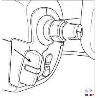
Radio control satellite
Radio aerial
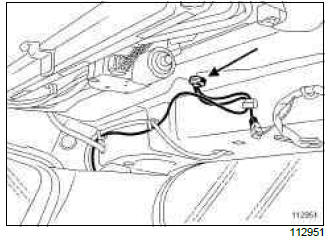
The radio aerial is located on the roof in the rear section.
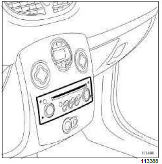
Radio
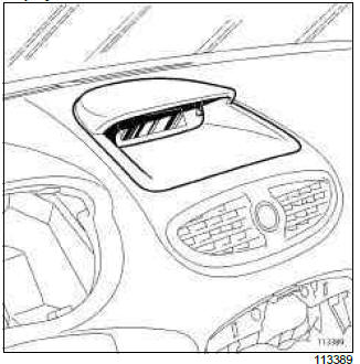
Display
Tweeter
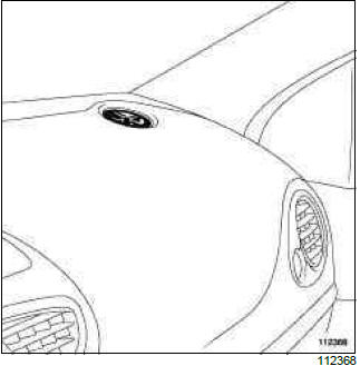
Front speaker
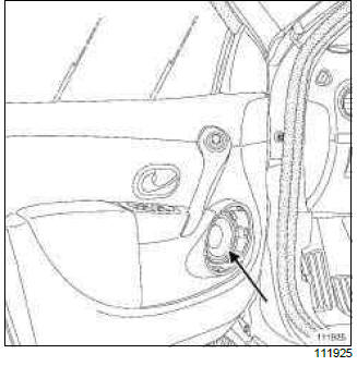
B85 or K85
Rear speaker
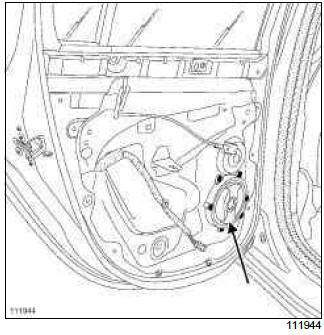
C85 or S85
Rear speaker
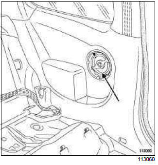
RADIO NO. 05
Tuner-amplifier
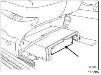
The receiver is located under the front right-hand seat.
RADIO NO. 08
Offset multimedia socket
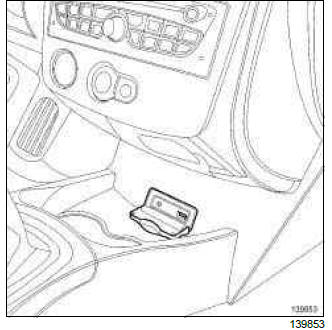
Offset multimedia socket computer
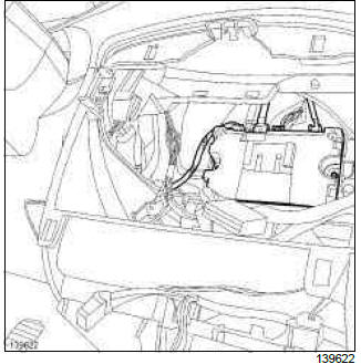
The offset multimedia socket computer is located behind the dashboard centre front panel.
Radio: Before/after repair procedure
The radio is protected by a four-digit code.
ENTERING THE RADIO ANTI-THEFT CODE
RADIO NO. 01
- Switch on the ignition.
- Switch the radio on.
- Wait until 0000 appears on the central display and the first 0 flashes.
1 - Entering the code using the steering column control
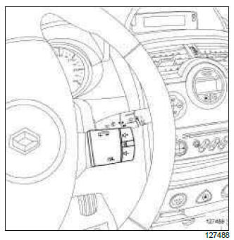
- Display the first digit by pressing the + or - buttons
on the steering column switch.
Confirm this digit by pressing the wheel on the steering column control.
Press on the right-hand button of the steering column control to move on to the second digit.
- Display the second digit by pressing the + or - buttons
on the steering column control.
Confirm this digit by pressing the wheel on the steering column control.
Press on the right-hand button of the steering column control to move on to the third digit.
- Display the third digit by pressing the + or - buttons
on the steering column control.
Confirm this digit by pressing the wheel on the steering column control.
Press on the right-hand button of the steering column control to move on to the fourth digit.
- Display the fourth digit by pressing the + or - buttons
on the steering column control.
Confirm this digit by pressing the wheel on the steering column control.
Keep the wheel pressed to transfer this code to the radio. As soon as the operation is complete, the confirmation beep will sound.
- If the code entered is correct, the radio operates.
- If the code is incorrect, the word CODE appears on the display.
- Wait until 0000 appears on the screen and repeat the operations again.
2 - Entering the code using the radio
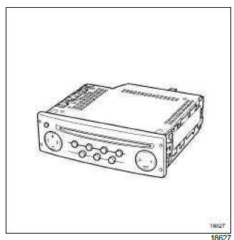
- Press on button 1 of the keypad until the desired
number is obtained for the first digit.
Press on button 2 of the keypad until the desired number is obtained for the second digit.
Press on button 3 of the keypad until the desired number is obtained for the third digit.
Press on button 4 of the keypad until the desired number is obtained for the fourth digit.
- As soon as the code is correctly displayed, press and hold button 6 on the keypad to transfer this code to the radio. As soon as the operation is complete, the confirmation beep will sound.
- If the code entered is correct, the radio operates.
- If the code is incorrect, the word CODE appears on the display.
- Wait until 0000 appears on the screen and repeat the operations again.
RADIO NO. 02 or RADIO NO. 03 or RADIO NO.04 or RADIO NO. 05 or RADIO NO. 06 or RADIO NO. 07 or RADIO NO. 08
- Switch on the ignition.
- Switch the radio on.
- Wait until RADIO CODE 0000 appears on the central display and the first 0 flashes.
3 - Entering the code using the steering column control
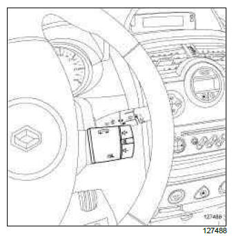
- Display the first digit by pressing the + or - buttons
on the steering column switch.
Press on the right-hand button of the steering column control to move on to the second digit.
- Display the second digit by pressing the + or - buttons
on the steering column control.
Press on the right-hand button of the steering column control to move on to the third digit.
- Display the third digit by pressing the + or - buttons
on the steering column control.
Press on the right-hand button of the steering column control to move on to the fourth digit.
- Display the fourth digit by pressing the + or - buttons
on the steering column control.
Keep the OK button pressed to transfer this code to the radio. As soon as the operation is complete, the confirmation beep will sound.
- If the code entered is correct, the radio operates.
- If the code is incorrect, the words ERROR CODE appear on the display.
- Wait until RADIO CODE 0000 appears on the screen and repeat the operations again.
4 - Entering the code using the rotary button on the radio
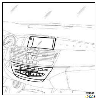
- Display the first digit by turning the rotary button on
the radio.
Press the right-hand button to move on to the second digit.
- Display the second digit by turning the rotary button
on the radio.
Press the right-hand button to move on to the third digit.
- Display the third digit by turning the rotary button on
the radio.
Press the right-hand button to move on to the fourth digit.
- Display the fourth digit by turning the rotary button
on the radio.
Keep the OK button pressed to transfer this code to the radio. As soon as the operation is complete, the confirmation beep will sound.
- If the code entered is correct, the radio operates.
- If the code is incorrect, the words ERROR CODE appear on the display.
- Wait until RADIO CODE 0000 appears on the screen and repeat the operations again.
5 - Entering the code using the radio
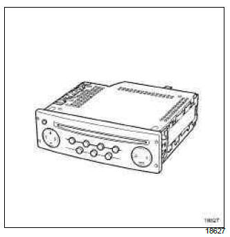
- Press on button 1 of the keypad until the desired
number is obtained for the first digit.
Press on button 2 of the keypad until the desired number is obtained for the second digit.
Press on button 3 of the keypad until the desired number is obtained for the third digit.
Press on button 4 of the keypad until the desired number is obtained for the fourth digit.
- As soon as the code is correctly displayed, press and hold button 6 on the keypad to transfer this code to the radio. As soon as the operation is complete, the confirmation beep will sound.
- If the code entered is correct, the radio operates.
- If the code is incorrect, the words ERROR CODE appear on the display.
- Wait until RADIO CODE 0000 appears on the screen and repeat the operations again.
Radio: Removal - Refitting
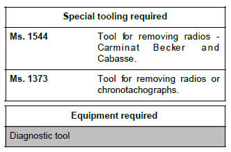
REMOVAL
I - REMOVAL PREPARATION OPERATION
RADIO NO. 07
- If replacing, carry out the necessary operations using the Diagnostic tool (see Fault finding - Replacement of components) (86A, R01-08).
RADIO NO. 08
- If replacing, carry out the necessary operations using the Diagnostic tool (see Fault finding - Replacement of components) (86A, R02-08).
- Switch off the ignition.
II - OPERATION FOR REMOVAL OF PART CONCERNED
RADIO NO. 05
CD multichanger radio
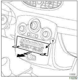
- Remove the radio (1) using the (Ms. 1544).
RADIO NO. 01 or RADIO NO. 02 or RADIO NO.03 or RADIO NO. 04 or RADIO NO. 06 or RADIO NO. 07 or RADIO NO. 08
Single CD radio
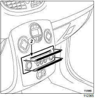
- Remove the radio (2) using the two (Ms. 1373).
- Disconnect the audio equipment connectors.
WARNING
To ensure correct operation:
- do not pinch the aerial cable,
- do not bend the aerial cable,
- do not force the aerial cable when refitting.
- Disconnect the aerial.
REFITTING
I - REFITTING OPERATION FOR PART CONCERNED
WARNING
To ensure correct operation:
- do not pinch the aerial cable,
- do not bend the aerial cable,
- do not force the aerial cable when refitting.
- Connect the aerial.
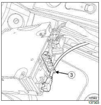
- Clip on the aerial wiring at (3).
- Connect the radio connectors.
- Refit the radio.
II - FINAL OPERATION
- Carry out the necessary operations (see Fault finding - Replacement of components) (86A, Radio).
RADIO NO. 07
- If replacing, carry out the necessary operations using the Diagnostic tool (see Fault finding - Replacement of components) (86A, R01-08).
RADIO NO. 08
- If replacing, carry out the necessary operations using the Diagnostic tool (see Fault finding - Replacement of components) (86A, R02-08).
Radio aerial: Removal - Refitting
REMOVAL
I - REMOVAL PREPARATION OPERATION
- Depending on the equipment level of the vehicle, remove the covers for the interior rear-view mirror in order to disconnect the rain sensor connector (see 85A, Wiping - Washing, Rain and light sensor: Removal - Refitting, 85A-5).
- Remove the headlining (see Headlining: Removal - Refitting) (MR 393, 71A, Body internal trim).
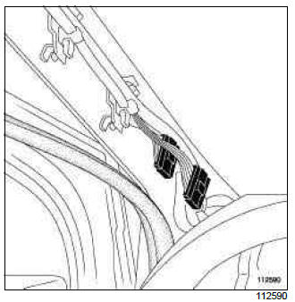
- Carefully disconnect the various connectors.
- Remove the right-hand rear quarter panel trim (see Quarter panel trim: Removal - Refitting) (MR 393, 71A, Body internal trim).
II - OPERATION FOR REMOVAL OF PART CONCERNED
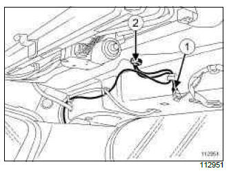
- Unclip the connector (1).
- Remove the bolt (2).
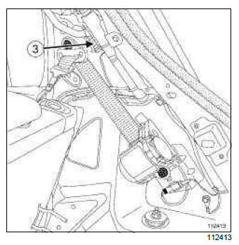
- Unclip the connector(s) (depending on the version) from the union board (3).
- Remove the aerial.
REFITTING
I - REFITTING OPERATION FOR PART CONCERNED
- Refit the aerial.
- Tighten the bolt (2).
Note: Make sure that the wiring is in good condition.
- Clip the connectors in place.
II - FINAL OPERATION.
- Refit the headlining (see Headlining: Removal - Refitting) (MR 393, 71A, Body internal trim).
- Depending on the level of equipment of the vehicle, reconnect the rain sensor connector.
- Depending on the equipment level of the vehicle, refit the interior rear-view mirror covers (see 85A, Wiping - Washing, Rain and light sensor: Removal - Refitting, 85A-5).
- Refit the right-hand rear quarter panel trim (see Quarter panel trim: Removal - Refitting) (MR 393, 71A, Body internal trim).
Tweeter: Removal - Refitting
REMOVAL
I - REMOVAL PREPARATION OPERATION
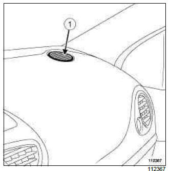
- Unclip the tweeter grille using a flat-blade screwdriver (1).
II - OPERATION FOR REMOVAL OF PART CONCERNED
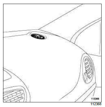
- Unclip:
- the tweeter,
- the connector.
REFITTING
I - REFITTING OPERATION FOR PART CONCERNED
- Clip on:
- the connector,
- the tweeter.
II - FINAL OPERATION
- Clip on the tweeter grille.
Front speakers: Removal - Refitting
REMOVAL
I - REMOVAL PREPARATION OPERATION
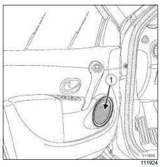
- Remove the front speaker grille (1).
II - OPERATION FOR REMOVAL OF PART CONCERNED
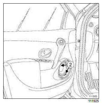
- Remove:
- the bolts (2),
- the front speaker.
- Disconnect the connector.
REFITTING
I - REFITTING OPERATION FOR PART CONCERNED
- Connect the connector,
- Refit:
- the front speaker,
- the bolts (2).
II - FINAL OPERATION
- Clip on the front speaker grille.
Rear speakers: Removal - Refitting
REMOVAL
I - REMOVAL PREPARATION OPERATION
B85 or K85
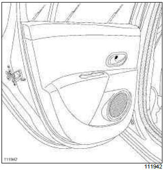
- Remove the rear door trim (see Rear side door trim: Removal - Refitting) (MR 393, 72A, Side opening element trim).
C85 or S85
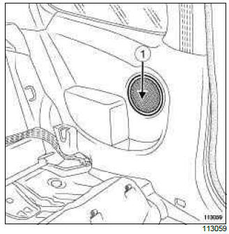
- Unclip the rear speaker grille (1).
II - OPERATION FOR REMOVAL OF PART CONCERNED
B85 or K85
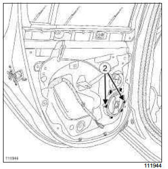
- Remove:
- the bolts (2),
- the rear speaker.
- Disconnect the connector.
C85 or S85
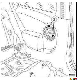
- Remove:
- the bolts (3),
- the rear speaker.
- Disconnect the connector.
REFITTING
I - REFITTING OPERATION FOR PART CONCERNED
B85 or K85
- Connect the connector,
- Refit:
- the rear speaker,
- the bolts (2).
C85 or S85
- Connect the connector.
- Refit:
- the rear speaker,
- the bolts (3).
II - FINAL OPERATION.
B85 or K85
- Refit the rear door trim (see Rear side door trim: Removal - Refitting) (MR 393, 72A, Side opening element trim).
C85 or S85
- Clip in the rear speaker grille (1).
Display: Removal - Refitting

REMOVAL
I - REMOVAL PREPARATION OPERATION
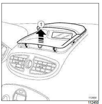
- Unclip the display mounting (1) using the (Car.1597).
- Disconnect the connectors.
II - OPERATION FOR REMOVAL OF PART CONCERNED
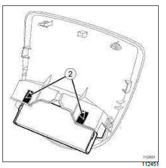
- Unclip the display at (2).
REFITTING
I - REFITTING OPERATION FOR PART CONCERNED
- Clip the display onto the mounting.
II - FINAL OPERATION.
- Connect the connectors.
- Clip on the display mounting.
Radio control satellite: Removal - Refitting
REMOVAL
OPERATION FOR REMOVAL OF PART CONCERNED
Note: The satellite radio control and the wiper stalk form a single inseparable part.
- Remove the wiper switch (see 84A, Control - Signals, Screen wiper switch: Removal - Refitting, 84A-8).
REFITTING OPERATION FOR PART CONCERNED
- Refit the wiper switch (see 84A, Control - Signals, Screen wiper switch: Removal - Refitting, 84A-8).
Receiver: Removal - Refitting
RADIO NO. 05

REMOVAL
I - REMOVAL PREPARATION OPERATION
- Remove the cover from the tuner-amplifier compartment.
II - REMOVAL OPERATION FOR THE PART CONCERNED
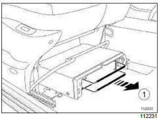
- Remove the receiver (1) using two (Ms. 1373).
- Disconnect the connectors.
REFITTING
I - REFITTING OPERATION FOR PART CONCERNED
- Connect the connectors.
- Refit the receiver.
II - FINAL OPERATION
- Refit the cover for the tuner-amplifier compartment.
Offset multimedia socket: Removal - Refitting
RADIO NO. 01 or RADIO NO. 02 or RADIO NO. 03 or RADIO NO. 04
REMOVAL
OPERATION FOR REMOVAL OF PART CONCERNED
- Open the glovebox.
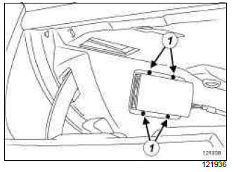
- Remove:
- the offset audio unit bolts (1),
- the offset audio unit.
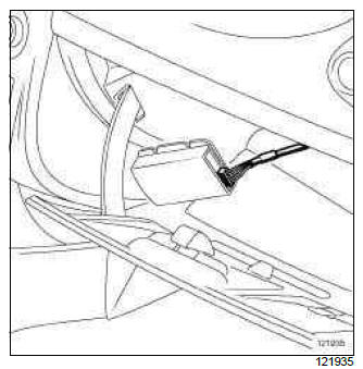
- Disconnect the offset audio unit connector.
REFITTING
REFITTING OPERATION FOR PART CONCERNED
Note: When replacing the offset audio unit, replace the wiring harness and check that the wiring harness runs correctly to the radio.
- Connect the offset audio unit connector.
- Refit:
- the offset audio unit,
- the offset audio unit bolts.
RADIO NO. 08
REMOVAL
I - REMOVAL PREPARATION OPERATION
- Switch off the ignition.
- Remove the centre console (see Centre console: Removal - Refitting) (57A, Interior equipment).
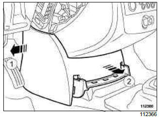
- Unclip the lower centre trim at (1) and (2).
- Disconnect the offset multimedia socket connectors.
- Remove the lower centre trim.
II - OPERATION FOR REMOVAL OF PART CONCERNED
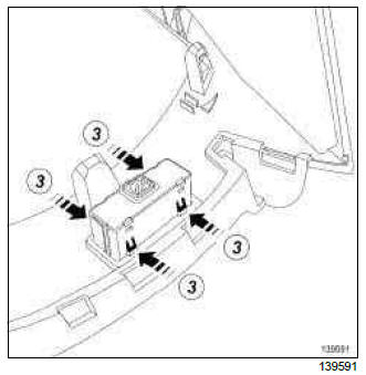
- Remove the offset multimedia socket by pressing on the clips at (3).
REFITTING
I - REFITTING OPERATION FOR PART CONCERNED
- Clip the offset multimedia socket onto the lower centre trim.
II - FINAL OPERATION
- Fit the lower centre trim.
- Connect the offset multimedia socket connectors.
- Clip on the lower centre trim.
- Refit the centre console (see Centre console: Removal - Refitting) (57A, Interior equipment).
Offset multimedia socket computer: Removal - Refitting
RADIO NO. 08

REMOVAL
I - REMOVAL PREPARATION OPERATION
- Disconnect the battery (see 80A, Battery, Battery: Removal - Refitting, 80A-1).
- Remove:
- the radio (see 86A, Radio, Radio: Removal - Refitting, 86A-8),
- the central console (see Centre console: Removal - Refitting) (57A, Interior equipment).
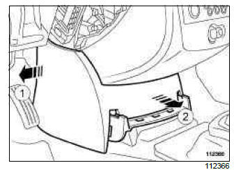
- Unclip the lower centre trim at (1) and (2).
- Disconnect the offset multimedia socket connectors.
- Remove:
- the centre front panel (see Centre front panel: Removal - Refitting) (57A, Interior equipment),
- the control panel (see Control panel: Removal - Refitting) (61A, Heating).
II - OPERATION FOR REMOVAL OF PART CONCERNED
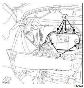
- Remove the bolts (3) from the offset multimedia socket computer.
- Separate the offset multimedia socket computer from its housing.
- Disconnect the offset multimedia socket computer connectors (4).
- Remove the offset multimedia socket computer.
REFITTING
I - REFITTING OPERATION FOR PART CONCERNED
- Fit the offset multimedia socket computer.
- Connect the offset multimedia socket computer connectors.
- Refit the offset multimedia socket computer.
II - FINAL OPERATION
- Refit:
- the control panel (see Control panel: Removal - Refitting) (61A, Heating),
- the centre front panel (see Centre front panel: Removal - Refitting) (57A, Interior equipment).
- Fit the lower centre trim.
- Connect the offset multimedia socket connectors.
- Clip on the lower centre trim.
- Refit:
- the central console (see Centre console: Removal - Refitting) (57A, Interior equipment),
- the radio (see 86A, Radio, Radio: Removal - Refitting, 86A-8).
- Connect the battery (see 80A, Battery, Battery: Removal - Refitting, 80A-1).
- Carry out the necessary operations using the Diagnostic tool (see Fault finding - Replacement of components) (86A, Radio).

