Renault Clio: Scuttle side panel: General description
Note: The information contained in the following describes the general repair procedure for all vehicles having the same design for this part.
Before reading the following general information, make sure that there are no special notes associated with the vehicle. These special notes are specified if necessary in other parts of the sub-section dealing with the component.
Note: For a detailed description of a particular connection, see MR 400.
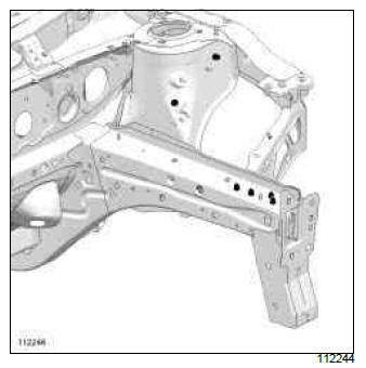
I - DESIGN OF THE STRUCTURAL COMPONENT
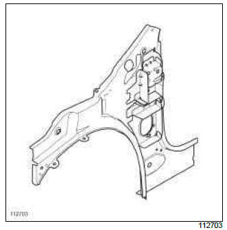
The special feature of this part it that it concurrently serves two functions:
- scuttle side panel,
- A-pillar lining.
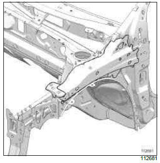
II - AREA TO BE CUT FOR PARTIAL REPLACEMENT
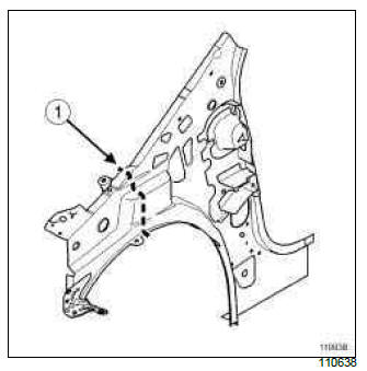
Cutting line (1) shows the area in which it is possible to make a cut.
This operation allows you to access the inside of the hollow section.
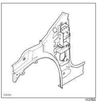
III - ASSEMBLY METHOD FOR A PARTIAL REPLACEMENT
Only the connections which are specific to the partial replacement by cutting are indicated.
WARNING
If the mating faces of the parts to be welded are not accessible, make EGW plug welds to replace the original resistance welds (see MR 400).
If there are other issues regarding access to mating faces, the various replacement options are described in the basic instructions for structural bodywork repair (see MR 400).

Line (5) on the diagram shows partial replacement and a weld by joggling with plug welds at regular intervals.
Depending on the exact position of the cut, EGW butt welding may also be used.
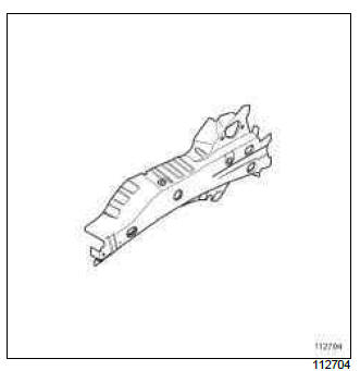
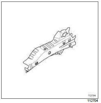
Scuttle side panel: Description
The options for replacing this part are as follows:
- partial replacement of front end section,
- partial replacement of the front section,
- complete replacement.
I - COMPOSITION OF THE SPARE PART
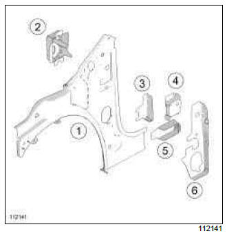
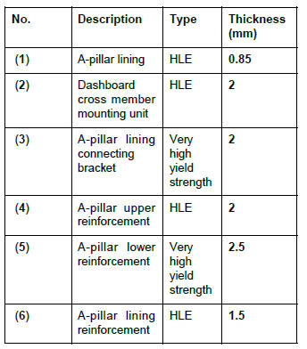
II - PART FITTED
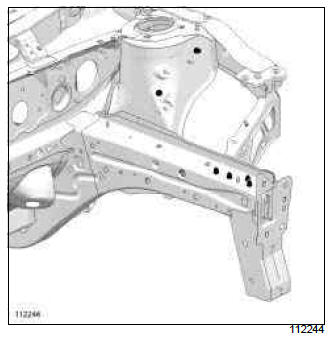
1 - Partial replacement of the front end section
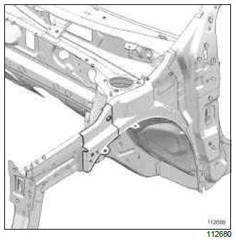
2 - Partial replacement of the front section
This cut gives access to the front wheel arch.
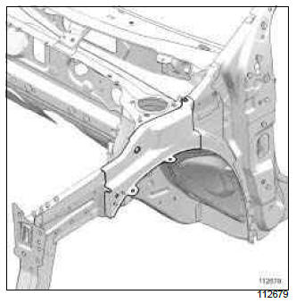
3 - Complete replacement
IMPORTANT
For welded connections in three thicknesses, the spot welds on the part replaced should be made in the same place as for the original joint to retain its mechanical properties.
III - POSITIONING OF LOCAL ELECTRICAL EARTHS
IMPORTANT
To avoid damaging the vehicles electric and electronic components, the battery and the earths of any wiring harness near the weld area must be disconnected.
The earth of the welding machine must be placed as close as possible to the weld area.
WARNING
If the spot welds cannot be made as they were originally using an electric spot welding machine, they should be replaced with plug welds after holes have been drilled in the first panel.
Upper reinforcement of scuttle side panel: General description
Note: The information contained in the following describes the general repair procedure for all vehicles having the same design for this part.
Before reading the following general information, make sure that there are no special notes associated with the vehicle. These special notes are specified if necessary in other parts of the sub-section dealing with the component.
Note: For a detailed description of a particular connection, see MR 400.
DESIGN OF THE STRUCTURAL COMPONENT
This type of part secures the front panel and the front wing upper mounting support.
Upper reinforcement of scuttle side panel: Description
There is only one way of replacing this part:
- complete replacement.
WARNING
If the spot welds cannot be made as they were originally using an electric spot welding machine, they should be replaced with plug welds after holes have been drilled in the first panel.
I - COMPOSITION OF THE SPARE PART
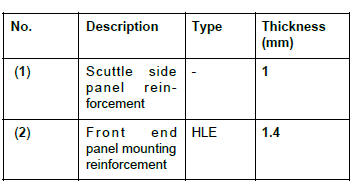
II - PART FITTED
IMPORTANT
For welded connections in three thicknesses, the spot welds on the part replaced should be made in the same place as for the original joint to retain its mechanical properties.
III - POSITIONING OF LOCAL ELECTRICAL EARTHS
IMPORTANT
To avoid damaging the vehicles electric and electronic components, the earths of any wiring harness near the weld area must be disconnected.
The earth of the welding machine must be placed as close as possible to the weld area.
READ NEXT:
 Front wheel arch: General description
IMPORTANT
Use a repair bench to ensure the positioning of the
points and the geometry of the axle assemblies.
Note:
The information contained in the following
describes the general repair procedure fo
Dashboard cross member: Removal - Refitting
Note:
In the event of a front impact with triggering of airbags,
check the area of connection between both
diameters of the beam. If there is any damage visible
to the naked eye, this part must be re
Side Upper Structure
A-pillar: General description
C85
WARNING
The information contained in the following
describes the general repair procedure for all vehicles
having the same design for this part.
Before reading the f
SEE MORE:
Master cylinder - front right-hand calliper brake pipe: Removal - Refitting
LEFT-HAND DRIVE, and WITHOUT ANTI-LOCK BRAKING SYSTEM
REMOVAL
I - REMOVAL PREPARATION OPERATION
Position the vehicle on a two-post lift (see Vehicle:
Towing and lifting) (MR 392, 02A, Lifting equipment).
Remove:
the engine cover,
the engine undertray,
the air filter unit air inlet pipe,
Master cylinder - front left-hand calliper brake pipe: Removal - Refitting
LEFT-HAND DRIVE, and WITHOUT ANTI-LOCK BRAKING SYSTEM
REMOVAL
I - REMOVAL PREPARATION OPERATION
Position the vehicle on a two-post lift (see Vehicle:
Towing and lifting) (MR 392, 02A, Lifting equipment).
Remove:
the engine cover,
the engine undertray,
the air filter box air inlet pipe,
