Renault Clio: Thermostat: Removal - Refitting
M4R
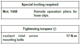
Note: This engine has two thermostats: one thermostat is located on the cylinder head and the other is on the cylinder block.
REMOVAL OF THE CYLINDER HEAD THERMOSTAT
I - REMOVAL PREPARATION OPERATION
- Position the vehicle on a two-post lift (see Vehicle: Towing and lifting) (MR 392, 02A, Lifting equipment).
- Remove the engine cover.
- Disconnect the battery (see Battery: Removal - Refitting) (MR 392, 80A, Battery).
- Remove the engine undertray.
- Drain the cooling system (see 19A, Cooling, Cooling system: Draining - Refilling, 19A-16).
- Remove the water chamber (see 19A, Cooling, Water chamber: Removal - Refitting, 19A-63).
II - REMOVAL OF PART CONCERNED
- Remove the cylinder head thermostat.
REFITTING THE CYLINDER HEAD THERMOSTAT
I - REFITTING PART CONCERNED
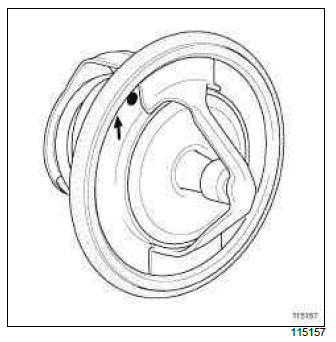
- Refit the cylinder head thermostat, respecting the direction indicated in the diagram.
II - FINAL OPERATION
- Refit the coolant outlet unit (see 19A, Cooling, Water chamber: Removal - Refitting, 19A-63).
- Connect the battery (see Battery: Removal - Refitting) (MR 392, 80A, Battery).
- Refit:
- the engine undertray,
- the engine cover.
- Carry out the following operations:
- fill the cooling system (see 19A, Cooling, Cooling system: Draining - Refilling, 19A-16),
- bleed the cooling system (see 19A, Cooling, Cooling system: Draining - Refilling, 19A-16).
REMOVAL OF THE CYLINDER BLOCK THERMOSTAT
I - REMOVAL PREPARATION OPERATION
- Position the vehicle on a two-post lift (see Vehicle: Towing and lifting) (MR 392, 02A, Lifting equipment).
- Remove the engine cover.
- Disconnect the battery (see Battery: Removal - Refitting) (MR 392, 80A, Battery).
- Remove the engine undertray.
- Drain the cooling system (see 19A, Cooling, Cooling system: Draining - Refilling, 19A-16).
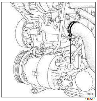
- Disconnect the coolant inlet union hose (1) using the (Mot. 1448).
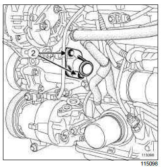
- Remove:
- the mounting bolts (2) from the coolant inlet union,
- the coolant outlet union.
II - REMOVAL OF PART CONCERNED
- Remove the cylinder block thermostat.
REFITTING THE CYLINDER BLOCK THERMOSTAT
I - REFITTING PART CONCERNED
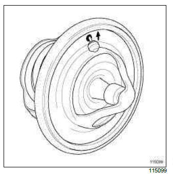
- Refit the cylinder block thermostat, respecting the direction indicated in the diagram.
II - FINAL OPERATION
- Tighten to torque the coolant inlet union mounting bolts (17 N.m).
- Connect the coolant inlet union hose using the (Mot.1448).
- Connect the battery (see Battery: Removal - Refitting) (MR 392, 80A, Battery).
- Refit:
- the engine undertray,
- the engine cover.
- Carry out the following operations:
- fill the cooling system (see 19A, Cooling, Cooling system: Draining - Refilling, 19A-16),
- bleed the cooling system .
D4F, and 784 or 786
REMOVAL
I - REMOVAL PREPARATION OPERATION
- Position the vehicle on a two-post lift (see Vehicle: Towing and lifting) (MR 392, 02A, Lifting equipment).
- Disconnect the battery (see Battery: Removal - Refitting) (MR 392, 80A, Battery).
- Remove:
- the engine cover,
- the water chamber (see 19A, Cooling, Water chamber: Removal - Refitting, 19A-63).
II - OPERATION FOR REMOVAL OF PART CONCERNED
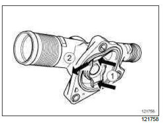
- Press on the spring mounting at (1).
- Turn the spring mounting at (2).
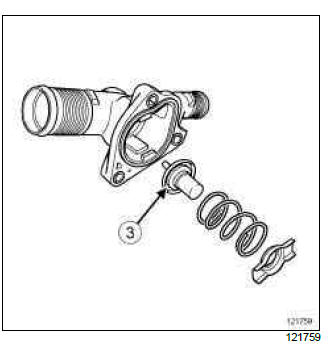
- Remove the thermostat (3).
REFITTING
I - REFITTING OPERATION FOR PART CONCERNED
- Refit the thermostat.
- Fit:
- the spring,
- the spring mounting.
- Press on the spring mounting.
- Turn the spring mounting.
II - FINAL OPERATION.
- Refit:
- the water chamber (see 19A, Cooling, Water chamber: Removal - Refitting, 19A-63),
- the engine cover.
- Connect the battery (see Battery: Removal - Refitting) (MR 392, 80A, Battery).
READ NEXT:
 Water chamber: Removal - Refitting
D4F, and 740 or 742 or 784
REMOVAL
I - REMOVAL PREPARATION OPERATION
Position the vehicle on a two-post lift (see Vehicle:
Towing and lifting) (MR 392, 02A, Lifting equipment).
Disconnect the bat
 Coolant temperature sensor: Removal - Refitting
REMOVAL
I - REMOVAL PREPARATION OPERATION
Disconnect the battery (see Battery: Removal - Refitting)
(80A, Battery).
Remove:
the engine cover,
the air intake sleeve.
II - OPERATION FOR REM
 Engine cooling fan assembly: Removal - Refitting
K9K
REMOVAL
I - REMOVAL PREPARATION OPERATION
Position the vehicle on a two-post lift (see Vehicle:
Towing and lifting) (MR 392, 02A, Lifting equipment).
Remove:
the engine cover,
the battery
SEE MORE:
 Side
Side
Side Airbags
This airbag may be fitted to each of the
front seats and is activated at the sides
of the seats (door side) to protect the
occupants in the event of a severe side
impact.
Depending on the vehicle, a marking on the windscreen informs you
of the presence of additional mean
 Front side door sliding window: Removal - Refitting
Note:
If the window is broken, replace the sealing film
(see Door sealing film: Removal - Refitting) (MR
393, 65A, Door sealing).
REMOVAL
I - REMOVAL PREPARATION OPERATION
Remove:
the door trim (see Front side door trim: Removal
- Refitting) (MR 393,72A, Side opening element
trim),
the int
© 2016-2026 Copyright Renault Clio Owners Club

