Renault Clio: Electro-hydraulic unit: Removal - Refitting
K9K, and JA5
REMOVAL
I - REMOVAL PREPARATION OPERATION
Note: When replacing the electric pump assembly, always replace the control relay.
IMPORTANT
Before any operation on the sequential system, discharge the accumulator using the Diagnostic tool.
- To discharge the accumulator, run command
" Discharge pressure accumulator " AC081.
To confirm the pressure drop, read the " Hydraulic pressure " parameter for the resulting value.
If there is still pressure in the accumulator, re-run the " Discharge pressure accumulator " command until the pressure is negligible and will not pose a risk when the high pressure pipes are removed.
The pressure reading must be close to zero.
- Position the vehicle on a two-post lift (see Vehicle: Towing and lifting) (MR 392, 02A, Lifting equipment).
K9K, and JA5
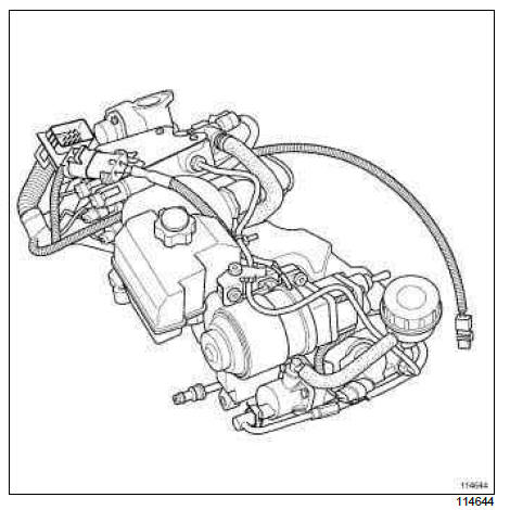
Note: The electro-hydraulic unit includes the pump assembly and the actuator module.
- Remove:
- the pump assembly (see 21B, Sequential gearbox, Pump assembly: Removal - Refitting, 21B-12),
- the actuator module (see 21B, Sequential gearbox, Actuator module: Removal - Refitting, 21B-34).
II - OPERATION FOR REMOVAL OF PART CONCERNED
- Remove the electro-hydraulic unit.
REFITTING
I - REFITTING OPERATION FOR PART CONCERNED
- Refit:
- the actuator module (see 21B, Sequential gearbox, Actuator module: Removal - Refitting, 21B-34),
- the pump assembly (see 21B, Sequential gearbox, Pump assembly: Removal - Refitting, 21B-12).
II - FINAL OPERATION
- Carry out the necessary programming (see Fault finding - Replacement of components) (MR 394, 21B, Sequential gearbox).
WARNING
After the accumulator has been fully filled (15 seconds after the ignition has been switched on): the oil is at the MIN mark.
D4F, and JA3
REMOVAL
I - REMOVAL PREPARATION OPERATION
Note: When replacing the electric pump assembly, always replace the control relay.
IMPORTANT
Before any operation on the sequential system, discharge the accumulator using the Diagnostic tool.
- To discharge the accumulator, run command
" Discharge pressure accumulator " AC081.
To confirm the pressure drop, read the " Hydraulic pressure " parameter for the resulting value.
If there is still pressure in the accumulator, re-run the " Discharge pressure accumulator " command until the pressure is negligible and will not pose a risk when the high pressure pipes are removed.
The pressure reading must be close to zero.
- Position the vehicle on a two-post lift (see Vehicle: Towing and lifting) (MR 392, 02A, Lifting equipment).
D4F, and JA3
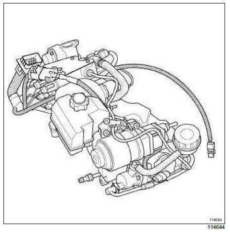
Note: The electro-hydraulic unit includes the pump assembly and the actuator module.
- Remove:
- the pump assembly (see 21B, Sequential gearbox, Pump assembly: Removal - Refitting, 21B-12),
- the actuator module (see 21B, Sequential gearbox, Actuator module: Removal - Refitting, 21B-34).
II - OPERATION FOR REMOVAL OF PART CONCERNED
- Remove the electro-hydraulic unit.
REFITTING
I - REFITTING OPERATION FOR PART CONCERNED
- Refit:
- the actuator module (see 21B, Sequential gearbox, Actuator module: Removal - Refitting, 21B-34),
- the pump assembly (see 21B, Sequential gearbox, Pump assembly: Removal - Refitting, 21B-12).
II - FINAL OPERATION
- Carry out the necessary programming (see Fault finding - Replacement of components) (MR 394, 21B, Sequential gearbox).
WARNING
After the accumulator has been fully filled (15 seconds after the ignition has been switched on): the oil is at the MIN mark.
READ NEXT:
 Pump assembly: Removal - Refitting
K9K, and JA5
REMOVAL
I - REMOVAL PREPARATION OPERATION
Note:
When replacing the electric pump assembly,
always replace the control relay.
IMPORTANT
Before any operation on the sequential system,
disc
Solenoid valves: Removal - Refitting
K9K, and JA5
REMOVAL
I - REMOVAL PREPARATION OPERATION
Note:
Before removing the solenoid valves, always
mark their respective connectors in order not to
mix them up.
IMPORTANT
Before any operation o
Engagement sensor: Removal - Refitting
K9K, and JA5
REMOVAL
I - REMOVAL PREPARATION OPERATION
Position the vehicle on a two-post lift (see Vehicle:
Towing and lifting) (MR 392, 02A, Lifting equipment).
Disconnect the battery (see Batt
SEE MORE:
Trip settings
The display of information shown below DEPENDS ON THE VEHICLE EQUIPMENT AND
COUNTRY
Examples of selections
Interpreting the display selected
a) Total mileage and trip mileage recorder.
b) Journey parameters.
Fuel used.
Fuel consumed since the last
Trip computer and warning system
Information messages
These can help in the vehicle starting phase, or give information about a
selection or a driving status.
Examples of information messages are given in the following pages.
Examples of messages
Interpreting the display selected
« PARKING BRAKE ON
