Renault Clio: F4R, and 830
REMOVAL
I - REMOVAL PREPARATION OPERATION
- Position the vehicle on a two-post lift (see Vehicle: Towing and lifting) (MR 392, 02A, Lifting equipment).
- Disconnect the battery (see Battery: Removal - Refitting) (MR 392, 80A, Battery).
- Perform the following operations:
- drain the engine oil (see 10A, Engine and cylinder block assembly, Engine oil: Draining - Refilling, 10A-12),
- drain the cooling system (see 19A, Cooling, Cooling system: Draining - Refilling, 19A-16).
- Remove:
- the throttle valve (see 12A, Fuel mixture, Throttle valve: Removal - Refitting, 12A-33),
- the intake distributor (see 12A, Fuel mixture, Inlet distributor: Removal - Refitting, 12A-45),
- the injector holder plate equipped with the injector rail (see 12A, Fuel mixture, Injector holder shim: Removal - Refitting, 12A-69),
- the ignition coils (see 17A, Ignition, Coils: Removal - Refitting, 17A-2),
- the oil decanter (see 11A, Top and front of engine, Oil decanter: Removal - Refitting, 11A-302),
- the battery (see Battery: Removal - Refitting) (MR 392, 80A, Battery),
- the air filter box (see 12A, Fuel mixture, Air filter unit: Removal - Refitting, 12A-17),
- the front right-hand wheel (see Wheel: Removal - Refitting) (MR 392, 35A, Wheels and tyres),
- the front bumper (see Front bumper: Removal - Refitting) (MR 393, Bodywork, 55A, Exterior protection),
- the accessories belt (see 11A, Top and front of engine, Accessories belt: Removal - Refitting, 11A-5),
- the timing belt (see 11A, Top and front of engine, Timing belt: Removal - Refitting, 11A-48).
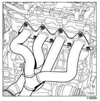
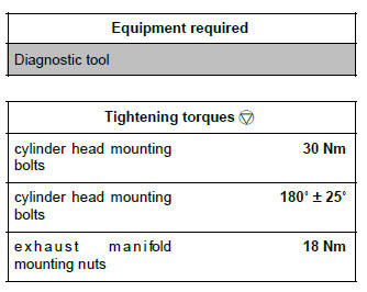
- Remove the mounting nuts from the exhaust manifold.
- Move aside the exhaust manifold.
- Remove:
- the exhaust manifold gasket,
- the rocker cover (see 11A, Top and front of engine, Rocker cover: Removal - Refitting, 11A-183),
- the inlet and exhaust camshafts.
II - OPERATION FOR REMOVAL OF PART CONCERNED
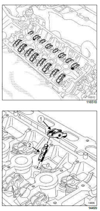
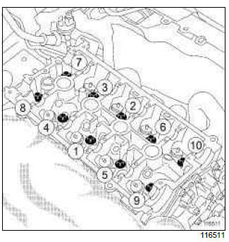
- Remove:
- the valve rockers (1),
- the hydraulic tappets (2).
Note: To prevent any risk of unpriming the hydraulic tappets make sure that they are vertical.
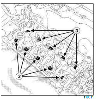
- Remove:
- the cylinder head mounting bolts (3),
- the cylinder head.
- Mount the cylinder head on the cylinder head support.
- Remove the cylinder head gasket.
REFITTING
I - REFITTING PREPARATIONS OPERATION
1 - CLEANING THE CYLINDER HEAD
- Clean the cylinder head.
IMPORTANT
Wear goggles with side protectors for this operation.
IMPORTANT
Wear latex gloves during the operation.
WARNING
Do not scratch the aluminium joint faces: any surface damage to the joint faces may cause leaks.
WARNING
The joint faces must be clean, dry and free from grease (avoid finger marks).
WARNING
Do not allow this product to drip onto the paintwork.
Clean the cylinder head carefully to prevent foreign bodies from entering the oil supply and return galleries.
Failure to follow this advice could lead to the blocking of the various oil inlet galleries, which would quickly result in engine damage.
- Clean the joint faces with SUPER CLEANER FOR
JOINT FACES to dissolve any part of the seal still
remaining on the cylinder head and cylinder block.
Apply the product to the part to be cleaned, wait approximately ten minutes then remove the residue with a wooden spatula.
2 - PREPARING TO FIT THE CYLINDER HEAD
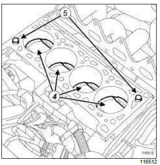
- Place the pistons at (4) half stroke.
- Check that the centring devices (5) are present and in good condition on the cylinder block.
II - REFITTING OPERATION FOR PART CONCERNED
- Refit:
- the new cylinder head gasket,
- the cylinder head,
- the new cylinder head bolts.
Tightening the cylinder head:
- First, torque tighten, in order the cylinder head mounting bolts (30 Nm).
- Then torque tighten, in order the cylinder head mounting bolts again (30 Nm).
- Angle tighten in order the cylinder head mounting
bolts (180
READ NEXT:
D4F D4F, and 740 or 742 or 764 Air inlet Air inlet trunking Air filter unit Motorised throttle valve Inlet manifold D4F, and 784 air inlet Air filter box air inlet pipe Air filter unit A Air inlet: Description
K4M - F4R REMOVAL I - REMOVAL PREPARATION OPERATION Position the vehicle on a two-post lift (see Vehicle: Towing and lifting) (02A, Lifting equipment). Remove: the battery (see Battery: Removal Air resonator: Removal - Refitting
SEE MORE:
The Renault Clio IV (2014-2019) offers a satisfying driving experience with its nimble handling and responsive performance. Its compact size and maneuverability make it well-suited for urban driving and tight parking spaces. The precise steering and suspension tuning provide a balanced and confident
Driving
The Renault Clio IV (2014-2019) is designed with your comfort in mind. It features a well-crafted interior with quality materials and thoughtful ergonomics. The seats offer excellent support and adjustability, providing a comfortable driving experience. The cabin is designed to minimize noise and vi
Your comfort
