Renault Clio: High pressure pipe between rail and injector: Removal - Refitting
K9K, and 764 or 772
WARNING
Before starting work on the vehicle, make sure you have:
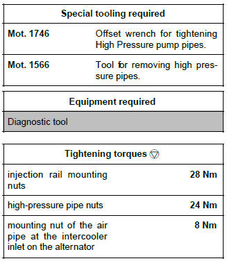
- a new blanking plug kit (part no. 77 01 476 857),
- cleaning wipes (part no. 77 11 211 707),
- cleaning product (part no. 77 11 224 188).
WARNING
Parts always to be replaced:
- all the high-pressure pipes which have been removed.
REMOVAL
I - REMOVAL PREPARATION OPERATION
- Position the vehicle on a lift (see Vehicle: Towing and lifting).
- Switch off the ignition and wait 30 seconds before starting work on the injection system.
IMPORTANT
Before carrying out any work on the injection system, check using the Diagnostic tool :
- that the rail is not under pressure,
- that the fuel temperature is not too high.
It is essential to respect the safety and cleanliness advice whenever work is carried out on this system (see 13B, Diesel injection, Diesel injection: Precautions for the repair, 13B-1).
- Disconnect the battery (see Battery: Removal - Refitting).
- Remove the engine cover.
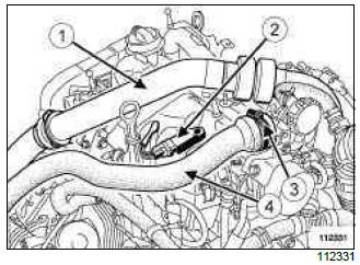
- Remove the upper part (1) of the turbocharger duct
- Disconnect the air inlet pressure sensor (2)
- Loosen the clip (3).
- Move the inlet duct to one side (4).
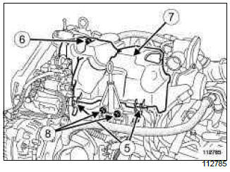
- Unclip the clips (5) from the injection rail protector cover.
- Remove:
- the injection rail protector cover mounting bolts (6),
- the injection rail protector cover (7),
- the dipstick,
- the dipstick pipe mounting bolts (8).
- Push the dipstick pipe to one side.
- Protect the alternator from fuel outflow.
- Pour cleaning product into a container.
IMPORTANT
Wear protective gloves when using cleaning product.
- Soak the brush with cleaning product, then clean the high-pressure pipe unions between the injection rail and the injectors
- Blast the cleaned areas with compressed air, then wipe them with new cleaning wipes.
IMPORTANT
Wear protective glasses.
WARNING
Do not blast with compressed air once the fuel circuit is open, otherwise impurities may enter the system. Use wipes if necessary.
II - REMOVAL OF PART CONCERNED
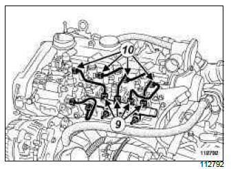
- Undo:
- the nut securing the high-pressure pipe between the injection rail and the injector at the rail end (9),
- the nut securing the high-pressure pipe between the injection rail and the injector at the injector end (10),
WARNING
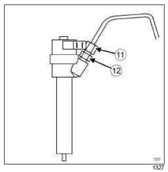
When the high-pressure pipe unions (11) on the injector holder are loosened, it is imperative to hold the filter rod retaining nut (12) with a lock wrench.
- Remove the high-pressure pipe in question and discard it.
Note: Be prepared for fuel outflow. Clean with new wipes.
- Insert the correct blanking plugs.
REFITTING
I - REFITTING PREPARATION OPERATION
- If replacing the four high-pressure pipes:
- remove the anti-splash cover mounting,
- Undo the injection rail mounting nuts by a few turns (the injection rail should be loose).
II - REFITTING PART CONCERNED
WARNING
Only remove the blanking plugs immediately before connecting the fuel circuit pipes.
The plugs are single-use. Do not reuse them.
- Take the new high-pressure pipe out of its plastic bag.
- Remove the blanking plugs from:
- the injection rail
- the injector fuel inlet.
Note: If the new pipe kit does not contain an applicator, lubrication of the nut threads will be unnecessary (as they are self-lubricating pipes).
- Finger tighten the high-pressure pipe nuts as much as possible, starting at the injection rail end.
- If replacing the four high-pressure pipes:
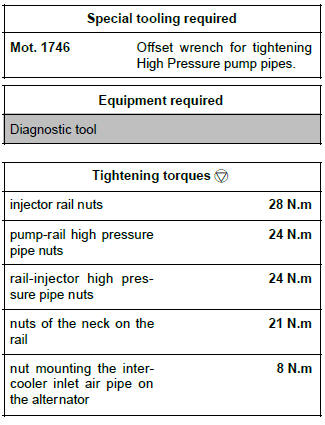
- Tighten to torque the injection rail mounting nuts (28 Nm),
- Refit the injection rail mounting.
- Tighten to torque the high-pressure pipe nuts (24 Nm) using (Mot. 1746) or (Mot. 1566) starting at the injection rail end.
III - FINAL OPERATION
- Refit:
- the dipstick pipe mounting bolts.
- the dipstick,
- the injection rail protector cover,
- the injection rail protector cover mountings.
- Loosen the mounting nut of the air pipe at the intercooler inlet on the alternator.
- Fit the air duct between the turbocharger and the intercooler air inlet pipe.
- Lock the air duct onto the turbocharger and the intercooler air inlet pipe.
- Tighten the bolt of the air duct on the rocker cover.
- Tighten to torque the mounting nut of the air pipe at the intercooler inlet on the alternator (8 Nm).
- Refit the air inlet duct and tighten its clip.
- Connect the inlet air pressure sensor
- Reprime the fuel circuit using the priming bulb.
- Connect the battery (see Battery: Removal - Refitting).
- Confirm that there is no diesel fuel leak:
- check the sealing after repair (see 13B, Diesel injection, High pressure pipe: Check, 13B- 99),
- accelerate several times at no load,
- check for leaks and for diesel fuel outflow.
- Use the Diagnostic tool to check for stored faults.
- Clear them if necessary.
K9K, and 750 or 752 or 766 or 768
IMPORTANT
Before carrying out any work on the injection system, check using the Diagnostic tool :
- that the injector rail is not under pressure,
- that the fuel temperature is not too high.
It is essential to respect the safety and cleanliness advice whenever work is carried out on this system.
Loosening a high pressure pipe union when the engine is running is prohibited.
WARNING
Before starting work on the vehicle, obtain:
- a new set of blanking plugs (part no.: 77 01 206 804),
- cleaning cloths (part no.: 77 11 211 707),
- cleaning product (part no.: 77 11 224 188).
Note: Vehicles equipped with the K9K*768 engine may or may not be equipped with an intercooler.
REMOVAL
I - REMOVAL PREPARATION OPERATION
- Disconnect the battery (see Battery: Removal - Refitting) 392, 80A, Battery).
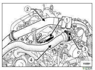
- Disconnect the inlet air pressure sensor (1).
K9K, and 750 or 766 or 768
- Remove the upper section of the turbocharger air duct (2).
- Loosen the clip (3).
- Move the inlet duct to one side (4).
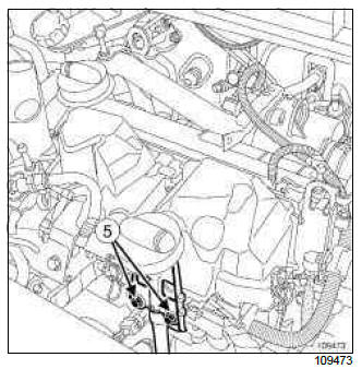
- Remove the dipstick bolts (5).
- Put the dipstick to one side.
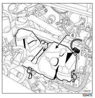
- Remove the injector rail protector cover (6).
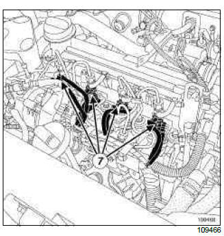
- Disconnect the following connectors (7) :
- the heater plugs,
- the injectors.
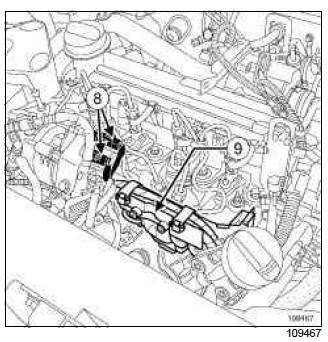
- Disconnect the high pressure pump electrical connectors (8).
- Remove the bolts mounting the neck (9) onto the spherical injector rail.
- Move the electric wiring harness and neck to the side as shown by the arrow.
- Loosen the injector rail nuts by several turns.
- Remove the clips connecting the high pressure pipes.
II - REMOVAL OF THE PART CONCERNED
- Undo:
- the high pressure pipe nut at the injector end using the (Mot. 1746),
- the high pressure pipe nut at the injector rail end using the (Mot. 1746).
- Fit blanking plugs into the openings.
REFITTING
I - REFITTING PREPARATION OPERATION
WARNING
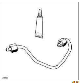
Before fitting a new high-pressure pipe, lightly lubricate the nut thread with oil from the applicator supplied in the new part.
Be careful not to allow oil into the high pressure pipe.
Do not lubricate high pressure pipes supplied without an applicator, as these high pressure pipes are self-lubricating.
WARNING
Do not remove the blanking plugs from each component until the last moment.
- replacing the four high pressure pipes:
- remove the anti-splash cover mounting,
- loosen the injector rail nuts by a few turns (the injector rail should be loose).
II - REFITTING OPERATION FOR PART CONCERNED
- Remove the blanking plugs.
- Insert the high pressure pipe olive in the injector high pressure inlet taper.
- Insert the high-pressure pipe olive in the rail high-pressure outlet taper.
- Fit the high pressure pipe nuts without tightening them, starting with the nut on the injector end.
- Slightly pretighten the high-pressure pipe nuts.
Note: The order of fitting of the rail - injector high pressure pipes is not important.
- Mount a new clip provided with the new high pressure pipe.
- If replacing the four high pressure pipes, torque tighten the injector rail nuts (28 N.m).
- Tighten to torque and in order the pump-rail high
pressure pipe nuts (24 N.m).
- pump end,
- rail end.
- Tighten to torque and in order the rail-injector high
pressure pipe nuts (24 N.m).
- injectors end,
- rail end.
Note: Tighten each pipe fully before moving on to the next pipe.
III - FINAL OPERATION
- Refit the neck on the injector rail and torque tighten the nuts of the neck on the rail (21 N.m).
- Connect the connectors of:
- the accelerometer,
- the injectors,
- the heater plugs.
- Refit the injector rail protector cover.
- Insert the dipstick.
- Refit the dipstick bolts.
- Refit the inlet duct and tighten its clip.
- Connect the inlet air pressure sensor.
K9K, and 750 or 766 or 768
- Loosen the intercooler inlet air pipe nut on the alternator.
- Fit the air duct between the turbocharger and the intercooler air inlet pipe.
- Lock the air duct onto the turbocharger and the intercooler inlet air pipe.
- Tighten the bolt of the air duct on the rocker cover.
- Torque tighten the nut mounting the intercooler inlet air pipe on the alternator (8 N.m).
- Connect the battery (see Battery: Removal - Refitting) 392, 80A, Battery).
- Prime the diesel circuit using the priming pump.
WARNING
Check that there are no diesel leaks:
- check the sealing after repair (see 13B, Diesel injection, High pressure pipe: Check, 13B-99),
- let the engine run at idle speed until the engine cooling fan starts to operate,
- accelerate several times at no load,
- carry out a road test,
- switch off the ignition,
- confirm that there is no diesel fuel leakage.

