Renault Clio: K9K, and 766 or 768
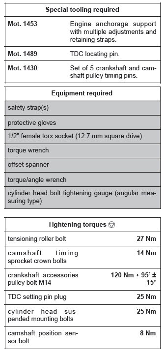
IMPORTANT
Wear protective gloves during the operation.
WARNING
Never rotate the engine anti-clockwise (timing end).
WARNING
Do not run the engine without the accessories belt so as not to damage the crankshaft accessories pulley.
I - PARTS TO BE SYSTEMATICALLY REPLACED
- the timing belt,
- the timing belt tensioning roller,
- the crankshaft accessories pulley bolt.
II - CONSUMABLES FOR REPAIR
- SILICONE ADHESIVE SEAL (see Vehicle: Parts and consumables for the repair) (MR 392, 04B, Consumables - Products).
REMOVAL
I - REMOVAL PREPARATION OPERATION
- Position the vehicle on a two-post lift (see Vehicle: Towing and lifting) (MR 392, 02A, Lifting equipment).
- Disconnect the battery (see Battery: Removal - Refitting) (MR 392, 80A, Battery).
- Remove:
- the front right-hand wheel (see Wheel: Removal - Refitting) (MR 392, 35A, Wheels and tyres),
- the front section of the front right-hand wheel arch liner (see Front wheel arch liner: Removal - Refitting) (MR 393, 55A, Exterior protection),
- the engine undertray,
- the lower engine tie-bar (see 19D, Engine mounting, Lower engine tie-bar: Removal - Refitting, 19D-13).
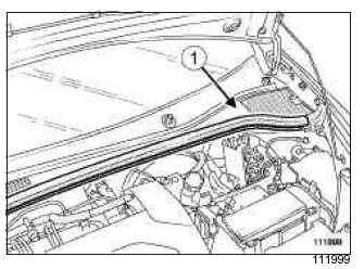
- Remove:
- the engine cover,
- the scuttle panel grille (1) (see Scuttle panel grille: Removal - Refitting) (MR 393, 56A, Exterior equipment),
- the scoop under the scuttle panel grille (see Scoop under the scuttle panel grille: Removal - Refitting) (MR 393, 56A, Exterior equipment).
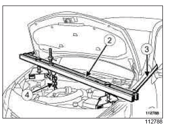
- Position the (Mot. 1453) (2) and hold it in place using a safety strap(s) (3).
- Fit a chain (4) on the lifting eye of the crankshaft end to enable the engine to be lifted using the (Mot.1453).
- Remove:
- the right-hand suspended engine mounting (see 19D, Engine mounting, Right-hand suspended engine mounting: Removal - Refitting, 19D-22),
- the accessories belt (see 11A, Top and front of engine, Accessories belt: Removal - Refitting, 11A-5).
Note: Do not damage the air conditioning pipes.
II - OPERATION FOR REMOVAL OF PART CONCERNED
- Fit protective gloves.
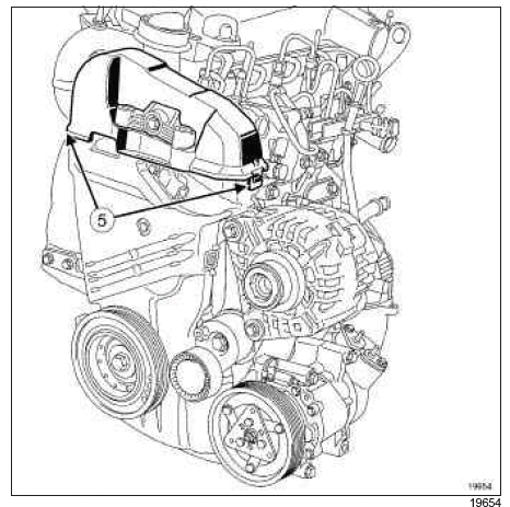
- Remove the upper timing cover by unclipping both tabs (5).
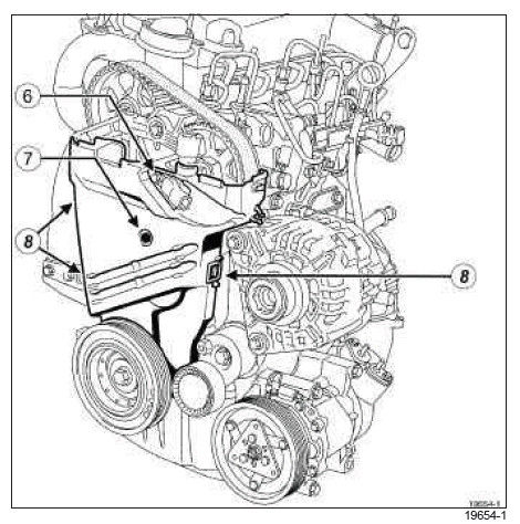
- Remove:
- the camshaft position sensor (6),
- the plastic bolt (7).
- Unclip the three tabs (8).
- Remove the lower timing cover.
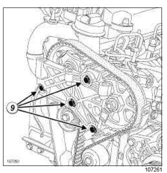
- Remove:
- the bolts (9) from the cylinder head suspended mounting,
- the cylinder head suspended mounting.
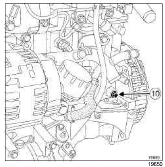
- Remove the TDC pin plug (10) using a 1/2" female torx socket (12.7 mm square drive) (14).
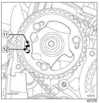
- Rotate the crankshaft clockwise (timing end) to position the hole (11) in the camshaft timing sprocket almost opposite the hole (12) in the cylinder head.
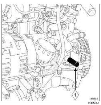
- Screw in the TDC setting pin (1) (Mot. 1489).
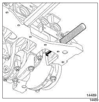
- Turn the crankshaft clockwise (timing end) smoothly until the crankshaft comes into contact with the TDC setting pin.
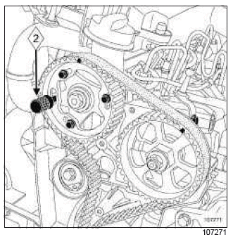
- Engage the pin (2) (Mot. 1430) in the camshaft timing sprocket and cylinder head holes.
- Remove:
- the camshaft timing sprocket setting pin (Mot.1430),
- the TDC setting pin (Mot. 1489).
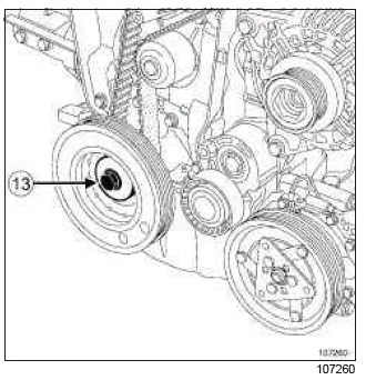
- Remove:
- the bolt (13) from the crankshaft accessories pulley, locking the engine flywheel with a large flat-blade screwdriver,
- the crankshaft accessories pulley.
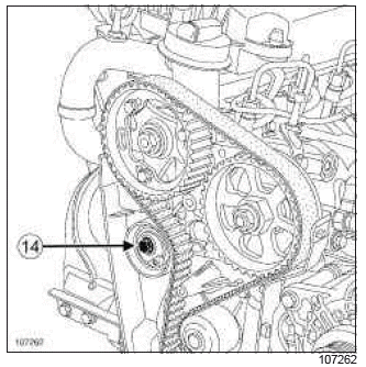
- Undo the tensioning roller bolt (14).
- Loosen the timing tension wheel by turning the eccentric cam using a 6 mm Allen key.
- Remove:
- the timing belt,
- the timing tensioning roller.
REFITTING
I - REFITTING OPERATION FOR PART CONCERNED
- Check:
- that there is no oil leak from the camshaft and crankshaft seals,
- the condition of the coolant pump (hard seal, play in the shaft, fluid leak, shaft rotation, (see Technical Note 3175A, Cooling system fault finding, 19A, Cooling, Cooling system - Fault finding chart ALP 8).
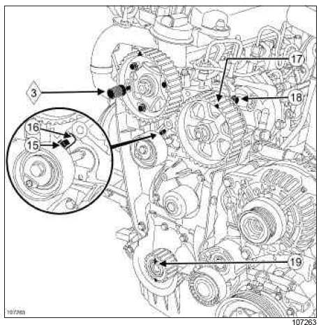
- Refit the timing tension wheel.
- Put the tensioning roller lug (15) in the cylinder head groove (16).
- Engage the pin (3) (Mot. 1430) in the camshaft timing sprocket and cylinder head holes, turning the camshaft using an 18 mm offset spanner if necessary.
- Check that the mark on the high pressure pump (17) is opposite the bolt head (18).
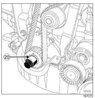
- Screw the old crankshaft accessories pulley bolt fitted with a spacer (20) (which does not cover the timing sprocket mark) into the crankshaft.
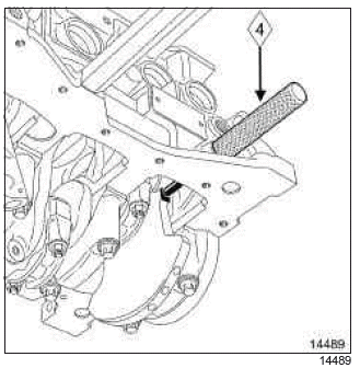
- Position the crankshaft so that it presses against the TDC setting pin (4) (Mot. 1489) (the crankshaft sprocket collet (19) must face upwards).
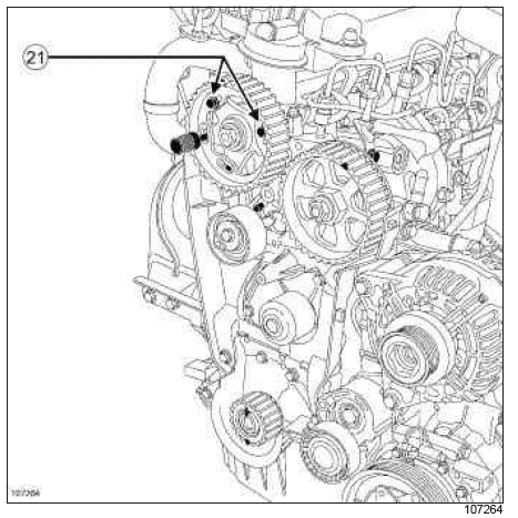
- Remove one bolt from the camshaft timing sprocket crown.
- Loosen the other two camshaft timing sprocket crown bolts (21) by one turn.
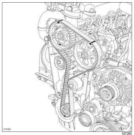
- Fit the timing belt, starting with the crankshaft sprocket, by aligning the marks on the belt with those on the crankshaft and camshaft sprockets, and the high pressure pump pinion.
Note: There should be 19 belt tooth grooves between the marks on the camshaft sprocket and the high pressure pump pinion, and 51 belt tooth grooves between the crankshaft sprocket and the high pressure pump pinion.
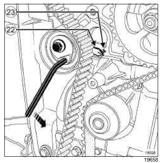
- Position the tensioning roller adjustable index marker (22) opposite the lug (23), turning the eccentric cam anti-clockwise using a 6 mm Allen key.
- Torque tighten the tensioning roller bolt (27 Nm) using a torque wrench.
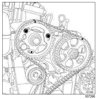
- Check that the camshaft timing sprocket crown bolts are not fully locked against the camshaft timing sprocket crown. If they are, repeat the timing belt refitting procedure.
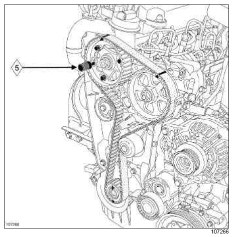
- Refit the bolt from the camshaft timing sprocket crown.
- Torque tighten the camshaft timing sprocket crown bolts (14 Nm) using a torque wrench.
- Remove:
- the TDC setting pin (Mot. 1489),
- the camshaft timing sprocket setting pin (5) (Mot.1430).
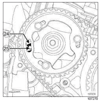
- Rotate the crankshaft clockwise through two revolutions
(timing end). Before the hole (24) in the camshaft
timing sprocket is opposite the hole (25) in the
cylinder head:
- screw the TDC setting pin (Mot. 1489) into the cylinder block,
- bring the crankshaft slowly and smoothly against the TDC setting pin.
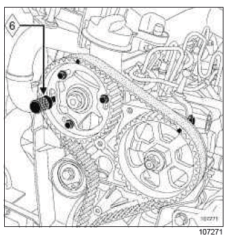
- Lock the camshaft timing sprocket using the (6) (Mot. 1430).
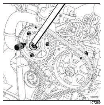
- If the pin (Mot. 1430) does not engage:
- loosen the camshaft timing sprocket crown bolts by a maximum of one turn,
- turn the camshaft timing sprocket hub using a offset spanner (18 mm) to set the camshaft timing sprocket hub,
- do not retighten the camshaft timing sprocket crown bolts.
- Loosen the camshaft timing sprocket crown bolts by a maximum of one turn.
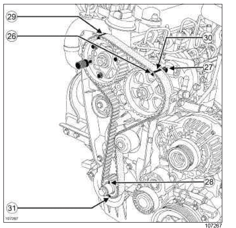
- Check:
- that the high pressure pump pinion mark (26) is opposite the bolt head (27),
- that the crankshaft timing sprocket collet (28) is positioned vertically at the top,
- that there are 19 belt tooth grooves between the marks on the camshaft sprocket (29) and the high pressure pump pinion (30),
- that there are 51 belt tooth grooves between the crankshaft sprocket marks (31) and the high pressure pump pinion (30).
Note: After two turns, the tensioning roller index markers may be in two different positions.
The rotation of the tensioning roller eccentric depends on the position.
First position
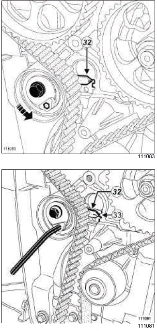
- Loosen the tensioning roller bolt by no more than one turn, holding it with a 6 mm Allen key.
- Gradually align the adjustable index (32) in the middle of the timing window (33), turning the key anticlockwise.
- Torque tighten:
- the tensioning roller bolt (27 Nm) using a torque wrench.
- the camshaft timing sprocket crown bolts (14 Nm) using a torque wrench.
Second position
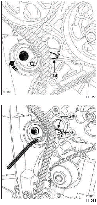
- Loosen the tensioning roller bolt by no more than one turn, holding it with a 6 mm Allen key.
- Gradually align the adjustable index (34) in the middle of the timing window (35), turning the key clockwise.
- Torque tighten:
- the tensioning roller bolt (27 Nm) using a torque wrench,
- the camshaft timing sprocket crown bolts (14 Nm) using a torque wrench.
- Remove the following tools:
- the TDC setting pin (Mot. 1489),
- the camshaft timing sprocket setting pin (Mot.1430).
- Rotate the crankshaft clockwise through two revolutions
(timing end). Before the hole in the camshaft timing
sprocket is opposite the hole in the cylinder
head:
- screw the TDC setting pin (Mot. 1489) into the cylinder block,
- bring the crankshaft slowly and smoothly against the TDC setting pin.
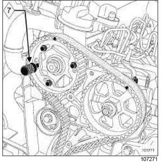
- Lock the camshaft timing sprocket using the (7) (Mot. 1430).
- If the pin does not engage, repeat the timing belt refitting operation.
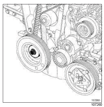
- Refit the accessories crankshaft pulley with a new bolt.
- Tighten to torque and angle (crankshaft in contact
with the TDC setting pin) the crankshaft accessories
pulley bolt M14 (120 Nm + 95

