Renault Clio: Left-hand suspended engine mounting: Removal - Refitting
K4M, and DP0
REMOVAL
I - REMOVAL PREPARATION OPERATION
- Remove:
- the scuttle panel grille (see Scuttle panel grille: Removal - Refitting) (MR 393, 56A, Exterior equipment),
- the scoop under the scuttle panel grille (see Scoop under the scuttle panel grille: Removal - Refitting) (MR 393, 56A, Exterior equipment),
- the battery (see Battery: Removal - Refitting) (MR 392, 80A, Battery),
- the battery tray (see Battery tray: Removal - Refitting) (MR 392, 80A, Battery),
- the air filter box (see 12A, Fuel mixture, Air filter unit: Removal - Refitting, 12A-17),
- the battery tray mounting (see Battery tray: Removal - Refitting) (MR 392, 80A, Battery),
- the computer and its mounting (see 17B, Petrol injection, Petrol injection computer: Removal - Refitting, 17B-37),
- the engine undertray.
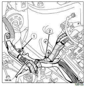
- Remove the wiring channel mounting nut (1).
- Detach the wiring channel (2).
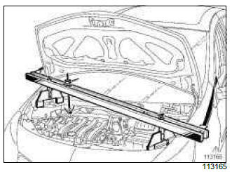
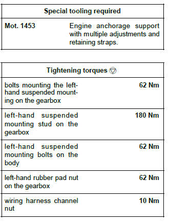
- Position tool (Mot. 1453).
- Mark the position of the suspended engine mounting on the body.
II - OPERATION FOR REMOVAL OF PART CONCERNED
- Remove:
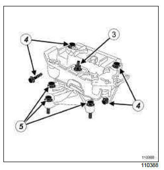
- the gearbox left-hand rubber pad mounting nut (3),
- the bolts (4) mounting the left-hand suspended mounting on the body,
- the left-hand suspended mounting from the body,
- the bolts (5) mounting the left hand suspended mounting on the gearbox,
- the gearbox left-hand suspended mounting.
REFITTING
I - REFITTING OPERATION FOR PART CONCERNED
- Reposition the left-hand suspended mounting on the gearbox.
- Refit the bolts mounting the left-hand suspended mounting on the gearbox.
- Torque tighten:
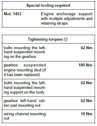
- the bolts mounting the left-hand suspended mounting on the gearbox (62 Nm),
- the gearbox suspended engine mounting stud (if it has been replaced) (180 Nm).
- Reposition the left-hand suspended mounting on the body.
- Refit the bolts mounting the left-hand suspended mounting on the body,
- Torque tighten:
- the bolts mounting the left-hand suspended mounting support on the body (62 Nm),
- the gearbox left-hand rubber pad mounting nut (62 Nm).
II - FINAL OPERATION.
- Remove the (Mot. 1453).
- Position the wiring channel.
- Torque tighten the wiring channel mounting nut (10 Nm).
- Refit:
- the computer and its mounting (see 17B, Petrol injection, Petrol injection computer: Removal - Refitting, 17B-37),
- the battery tray mounting (see Battery tray: Removal - Refitting) (MR 392, 80A, Battery),
- the air filter box (see 12A, Fuel mixture, Air filter unit: Removal - Refitting, 12A-17),
- the battery tray (see Battery tray: Removal - Refitting) (MR 392, 80A, Battery),
- the battery (see Battery: Removal - Refitting) (MR 392, 80A, Battery),
- the scoop under the scuttle panel grille (see Scoop under the scuttle panel grille: Removal - Refitting) (MR 393, 56A, Exterior equipment),
- the scuttle panel grille (see Scuttle panel grille: Removal - Refitting) (MR 393, 56A, Exterior equipment),
- the engine undertray.
- Connect the battery (see Battery: Removal - Refitting) (MR 392, 80A, Battery).
D4F, and JH3 - K9K - K4J, and JH3 - K4M, and JH3
REMOVAL
I - REMOVAL PREPARATION OPERATION
- Position the vehicle on a two-post lift (see Vehicle: Towing and lifting) (MR 392, 02A, Lifting equipment).
- Remove:
- the scuttle panel grille (see Scuttle panel grille: Removal - Refitting) (MR 393, 56A, Exterior equipment),
- the scoop under the scuttle panel grille (see Scoop under the scuttle panel grille: Removal - Refitting) (MR 393, 56A, Exterior equipment),
- the battery (see ) (MR 392, 80A, Battery),
- the battery tray (see Battery tray: Removal - Refitting) (MR 392, 80A, Battery),
- the air filter box (see 12A, Fuel mixture, Air filter unit: Removal - Refitting, 12A-17),
- the computer and its mounting (see 17B, Petrol injection, Petrol injection computer: Removal - Refitting, 17B-37),
- the engine undertray.
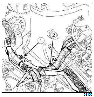
- Remove the wiring harness channel nut (1).
- Detach the wiring harness channel (2).
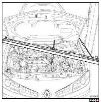
- Position tool (Mot. 1453).
- Mark the position of the suspended engine mounting on the body.
II - OPERATION FOR REMOVAL OF PART CONCERNED
D4F - K9K
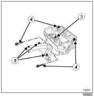
- Remove:
- the nut (3) from the gearbox left-hand rubber pad,
- the bolts (4) from the left-hand suspended mounting on the body,
- the left-hand suspended mounting from the body,
- the bolts (5) from the gearbox left-hand suspended mounting,
- the gearbox left-hand suspended mounting.
K4J - K4M, and 800
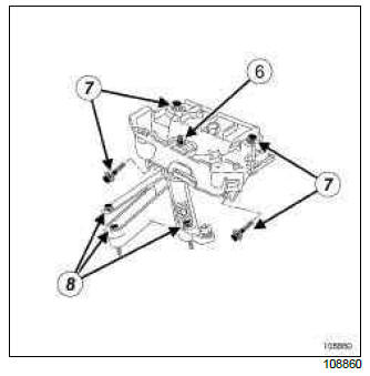
- Remove:
- the nut (6) from the gearbox left-hand rubber pad,
- the bolts (7) from the left-hand suspended mounting on the body,
- the left-hand suspended mounting from the body,
- the bolts (8) from the gearbox left-hand suspended mounting,
- the gearbox left-hand suspended mounting.
REFITTING
I - REFITTING OPERATION FOR PART CONCERNED
- Refit:
- the left-hand suspended mounting on the gearbox,
- the left hand suspended mounting bolts on the gearbox.
- Torque tighten:
- the bolts mounting the left-hand suspended mounting on the gearbox (62 Nm),
- If it has been replaced, the left-hand suspended mounting stud on the gearbox (180 Nm).
- Refit:
- the left-hand suspended mounting from the body,
- the left-hand suspended mounting bolts on the body.
- Torque tighten the left-hand suspended mounting bolts on the body (62 Nm).
- Refit the left-hand gearbox rubber pad nut.
- Tighten to torque the left-hand rubber pad nut on the gearbox (62 Nm).
II - FINAL OPERATION.
- Remove the (Mot. 1453).
- Position the wiring harness channel.
- Torque tighten the wiring harness channel nut (10 Nm).
- Refit:
- the computer and its mounting (see 17B, Petrol injection, Petrol injection computer: Removal - Refitting, 17B-37),
- the air filter box (see 12A, Fuel mixture, Air filter unit: Removal - Refitting, 12A-17),
- the battery tray (see Battery tray: Removal - Refitting) (MR 392, 80A, Battery),
- the battery (see ) (MR 392, 80A, Battery),
- the scoop under the scuttle panel grille (see Scoop under the scuttle panel grille: Removal - Refitting) (MR 393, 56A, Exterior equipment),
- the scuttle panel grille (see Scuttle panel grille: Removal - Refitting) (MR 393, 56A, Exterior equipment),
- the engine undertray.
M4R, and DP0
REMOVAL
I - REMOVAL PREPARATION OPERATION
- Fit the vehicle on a two-post lift (see Vehicle: Towing and lifting).
- Remove:
- the engine cover,
- the engine undertray,
- the battery ,
- the battery tray ,
- the right-hand mounting bolt from the radiator support cross member,
- the left-hand mounting bolt from the sub-frame tie-rod.
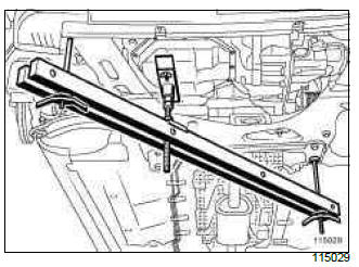
- Fit the lower engine support tool (Mot. 1672).
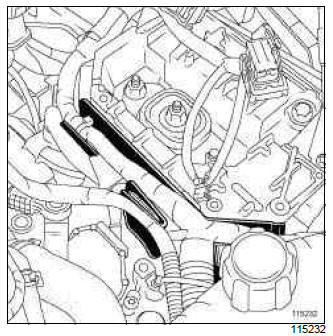
- Remove the gearbox mounting wiring harness neck.
II - REMOVAL OF PART CONCERNED
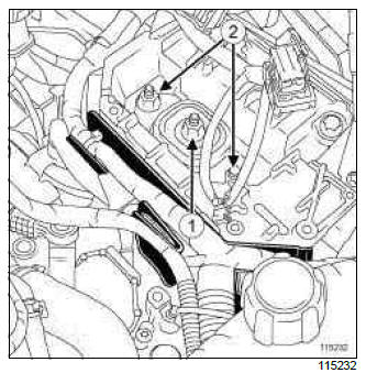
- Remove:
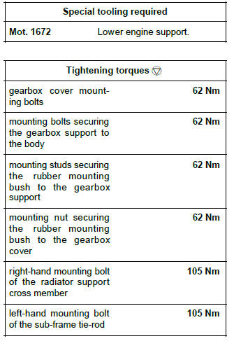
- the gearbox cover rubber mounting bush mounting nut (1),
- the gearbox support rubber mounting bush mounting studs (2),
- the rubber mounting bush.
Note: If necessary, lower the engine a few millimetres using (Mot. 1672) then hit the stud with a copper hammer.
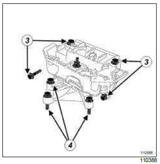
- Remove:
- the mounting bolts (3) securing the gearbox support on the body,
- the gearbox support,
- the mounting bolts (4) securing the gearbox cover to the gearbox,
- the gearbox cover.
REFITTING
I - REFITTING PART CONCERNED
- Refit:
- the gearbox cover,
- the gearbox cover mounting bolts,
- Tighten to torque the gearbox cover mounting bolts (62 Nm).
- Refit:
- the gearbox support,
- the mounting bolts securing the gearbox support to the body,
- the rubber mounting bush,
- the mounting studs securing the rubber mounting bush to the gearbox support,
- the mounting nut securing the rubber mounting bush to the gearbox cover.
- Tighten to torque:
- the mounting bolts securing the gearbox support to the body (62 Nm),
- the mounting studs securing the rubber mounting bush to the gearbox support (62 Nm),
- the mounting nut securing the rubber mounting bush to the gearbox cover (62 Nm).
II - FINAL OPERATION
- Fit the wiring harness neck to the gearbox support.
- Remove the lower engine support tool (Mot. 1672).
- Tighten to torque:
- the right-hand mounting bolt of the radiator support cross member (105 Nm),
- the left-hand mounting bolt of the sub-frame tie-rod (105 Nm).
- Refit:
- the battery tray ,
- the battery ,
- the engine cover,
- the engine undertray.
F4R
REMOVAL
I - REMOVAL PREPARATION OPERATION
- Position the vehicle on a two-post lift (see Vehicle: Towing and lifting) (MR 392, 02, Lifting equipment).
- Have to hand the gearbox side lifting eye and its mounting bolts (see 11A, Top and front of engine, Lifting eyes: Removal - Refitting, 11A-305).
- Disconnect the battery (see Battery: Removal - Refitting) (MR 392, 80A, Battery).
- Remove:
- the scuttle panel grille (see Scuttle panel grille: Removal - Refitting) (MR 393, 56A, Exterior equipment),
- the scoop under the scuttle panel grille (see Scoop under the scuttle panel grille: Removal - Refitting) (MR 393, 56A, Exterior equipment),
- the battery (see Battery: Removal - Refitting) (MR 392, 80A, Battery),
- the battery tray (see Battery tray: Removal - Refitting) (MR 392, 80A, Battery),
- the air filter box (see 12A, Fuel mixture, Air filter unit: Removal - Refitting, 12A-17),
- the battery tray mounting (see Battery tray: Removal - Refitting) (MR 392, 80A, Battery),
- the petrol injection computer (see 17B, Petrol injection, Petrol injection computer: Removal - Refitting, 17B-37).
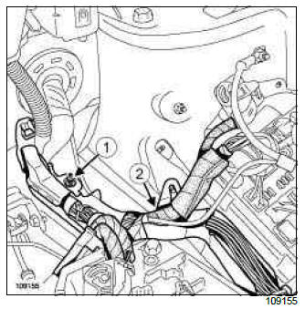
- Remove the wiring harness channel mounting nut (1).
- Move aside the wiring harness channel (2).
- Fit the gearbox side lifting eye (see 11A, Top and front of engine, Lifting eyes: Removal - Refitting, 11A-305).
- Fit the (Mot. 1453).
II - OPERATION FOR REMOVAL OF PART CONCERNED
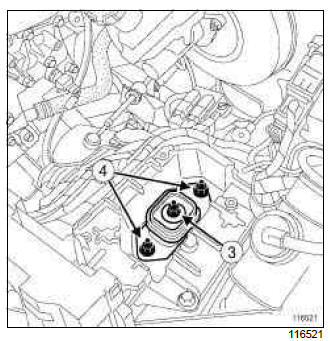
- Remove:
- the rubber pad mounting nut (3) from the left-hand suspended engine mounting,
- the rubber pad mounting bolt (4) from the left-hand suspended engine mounting,
- the rubber pad from the left-hand suspended engine mounting
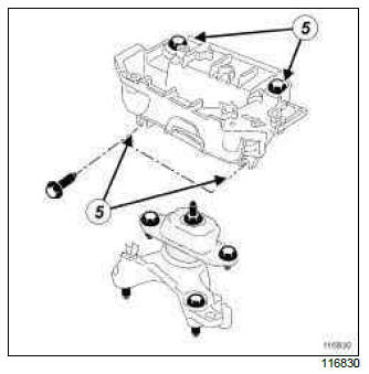
- Remove:
- the bolts (5) mounting the left-hand suspended engine mounting support on the body side,
- the left-hand suspended engine mounting support on the body side.
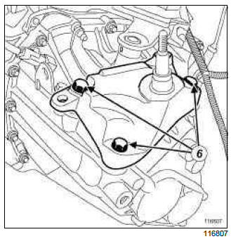
- Remove:
- the bolts (6) mounting the left-hand suspended engine mounting support on the gearbox side,
- the left-hand suspended engine mounting support on the gearbox side.
REFITTING
I - REFITTING OPERATION FOR PART CONCERNED
- Remove:
- the left-hand suspended engine mounting support on the gearbox side,
- the bolts mounting the left-hand suspended engine mounting support on the gearbox side.
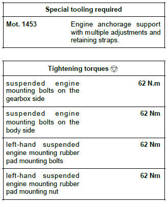
- Torque tighten the suspended engine mounting bolts on the gearbox side (62 N.m).
- Refit:
- the left-hand suspended engine mounting support on the body side,
- the bolts mounting the left-hand suspended engine mounting support on the body side.
- Torque tighten the suspended engine mounting bolts on the body side (62 Nm).
- Refit:
- the rubber pad on the left-hand suspended engine mounting,
- the rubber pad mounting bolt on the left-hand suspended engine mounting,
- the rubber pad mounting nut on the left-hand suspended engine mounting.
- Torque tighten:
- the left-hand suspended engine mounting rubber pad mounting bolts (62 Nm),
- the left-hand suspended engine mounting rubber pad mounting nut (62 Nm).
II - FINAL OPERATION.
- Remove:
- the (Mot. 1453),
- the gearbox side lifting eye (see 11A, Top and front of engine, Lifting eyes: Removal - Refitting, 11A-305).
- Fir the wiring harness channel.
- Refit:
- the wiring harness channel mounting nut,
- the petrol injection computer (see 17B, Petrol injection, Petrol injection computer: Removal - Refitting, 17B-37),
- the battery tray mounting (see Battery tray: Removal - Refitting) (MR 392, 80A, Battery),
- the air filter box (see 12A, Fuel mixture, Air filter unit: Removal - Refitting, 12A-17),
- the battery tray (see Battery tray: Removal - Refitting) (MR 392, 80A, Battery),
- the battery (see Battery: Removal - Refitting) (MR 392, 80A, Battery),
- the scoop under the scuttle panel grille (see Scoop under the scuttle panel grille: Removal - Refitting) (MR 393, 56A, Exterior equipment),
- the scuttle panel grille (see Scuttle panel grille: Removal - Refitting) (MR 393, 56A, Exterior equipment).
- Connect the battery (see Battery: Removal - Refitting) (MR 392, 80A, Battery).
- Refit the gearbox side lifting eye and its mounting bolts in the luggage compartment (see 11A, Top and front of engine, Lifting eyes: Removal - Refitting, 11A-305).
M4R, and TL4
REMOVAL
I - REMOVAL PREPARATION OPERATION
- Position the vehicle on a two-post lift (see Vehicle: Towing and lifting) (MR 392, 02, Lifting equipment).
- Remove:
- the engine cover,
- the engine undertray,
- the battery (see Battery: Removal - Refitting) (MR 392, 80A, Battery),
- the battery tray (see Battery tray: Removal - Refitting) (MR 392, 80A, Battery),
- the radiator mounting cross member left-hand bolt,
- the subframe tie-rod right-hand bolt.
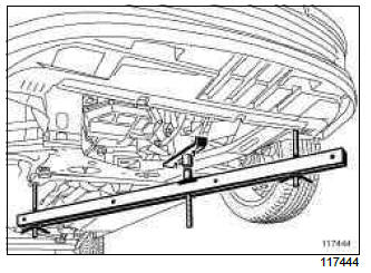
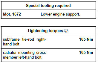
- Fit the lower engine support tool (Mot. 1672).
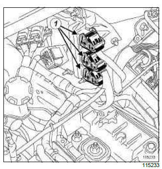
- Disconnect the injection computer connectors (1).
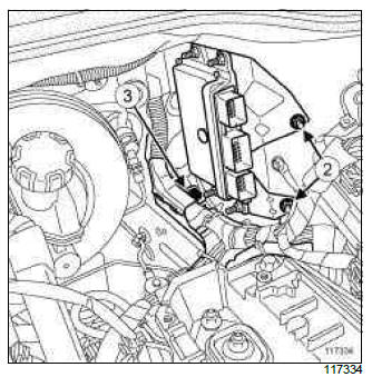
- Remove:
- the bolts (2) from the injection computer support,
- the bolt (3) from the wiring harness channel.
- Remove:
- the injection computer mounting,
- the wiring harness channel.
II - OPERATION FOR REMOVAL OF PART CONCERNED
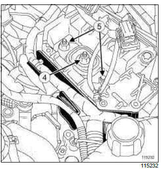
- Separate the wiring harness channel from the gearbox support.
- Remove:
- the nut (4) mounting the gearbox cover on the gearbox support,
- the bolts (5) from the gearbox support rubber mounting bush,
- the rubber mounting bush.
Note: If necessary, lower the engine a few millimetres using the (Mot. 1672) then hit the stud with a copper hammer.
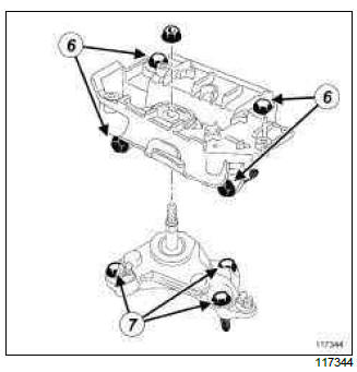
- Remove:
- the bolts (6) mounting the gearbox support on the body,
- the gearbox support,
- the bolts (7) mounting the gearbox cover on the gearbox,
- the gearbox cover.
REFITTING
I - REFITTING OPERATION FOR PART CONCERNED
- Refit:
- the gearbox cover,
- the bolts mounting the gearbox cover on the gearbox.
- Torque tighten the gearbox cover bolts (see 19D, Engine mounting, Suspended engine mounting: Tightening torque, 19D-1).
- Refit:
- the gearbox support,
- the gearbox support bolts on the body,
- the rubber mounting bush,
- the bolts to the gearbox support rubber mounting bush,
- the nut mounting the gearbox cover on the gearbox support.
- Tighten to torque and in order (see 19D, Engine
mounting, Suspended engine mounting: Tightening
torque, 19D-1) :
- the gearbox support bolts on the body,
- the bolts to the gearbox support rubber mounting bush,
- the nut mounting the gearbox cover on the gearbox support.
II - FINAL OPERATION.
- Fit the wiring harness channel to the gearbox support.
- Remove the lower engine support tool (Mot. 1672).
- Fit:
- the harness channel,
- the injection computer support.
- Refit:
- the injection computer support bolts,
- the wiring harness channel bolts.
- Connect the injection computer connectors.
- Refit:
- the subframe tie-rod right-hand bolt,
- the radiator mounting cross member left-hand bolt.
- Torque tighten:
- the subframe tie-rod right-hand bolt (105 Nm),
- the radiator mounting cross member left-hand bolt (105 Nm).
- Refit:
- the engine undertray,
- the battery tray (see Battery tray: Removal - Refitting) (MR 392, 80A, Battery),
- the battery (see Battery: Removal - Refitting) (MR 392, 80A, Battery),
- the engine cover.
K4M, and TL4
REMOVAL
I - REMOVAL PREPARATION OPERATION
- Position the vehicle on a two-post lift (see Vehicle: Towing and lifting) (02A, Lifting equipment).
- Remove:
- the engine undertray bolts,
- the engine undertray,
- the windscreen wiper arms (see Windscreen wiper arm: Removal - Refitting) (85A, Wiping - Washing),
- the scuttle panel grille (see Scuttle panel grille: Removal - Refitting) (56A, Exterior equipment),
- the scoop under the scuttle panel grille (see Scoop under the scuttle panel grille: Removal - Refitting) (56A, Exterior equipment),
- the front wheels (see Wheel: Removal - Refitting) (35A, Wheels and tyres),
- the front wheel arch liners (see Front wheel arch liner: Removal - Refitting) (55A, Exterior protection),
- the front bumper (see Front bumper: Removal - Refitting) (55A, Exterior protection).
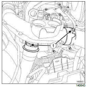
- Unclip the air inlet pipe from the air filter unit (1).
- Move aside the air inlet pipe from the air filter unit.
- Remove:
- the battery (see Battery: Removal - Refitting) (80A, Battery),
- the battery tray (see Battery tray: Removal - Refitting) (80A, Battery),
- the air filter unit (see 12A, Fuel mixture, Air filter unit: Removal - Refitting, 12A-17).
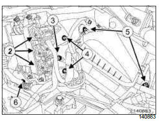
- Disconnect the connectors (2) from the petrol injection computer.
- Remove:
- the earth nut (3) on the body,
- the petrol injection computer nuts (4).
- Move aside the wiring of the petrol injection computer.
- Remove:
- the petrol injection computer,
- the Protection and Switching Unit nuts (5).
- Move aside the Protection and Switching Unit.
- Remove the wiring channel nut (6).
- Move aside the wiring channel on the body.
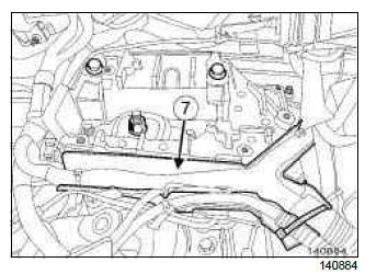
- Unclip the wiring channel (7) from the left-hand suspended engine mounting.
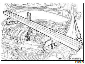
- Position the (Mot. 1453).
- Mark the position of the suspended engine mounting on the body using a indelible pencil.
II - OPERATION FOR REMOVAL OF PART CONCERNED
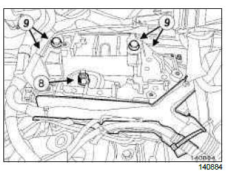
- Remove:
- the left-hand suspended engine mounting shaft nut (8),
- the bolts (9) of the left-hand suspended engine mounting support on the body,
- the left-hand suspended engine mounting support on the body.
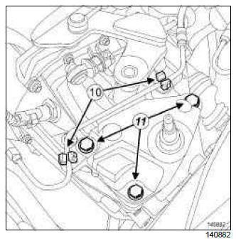
- Unclip the clutch pipe (10).
- Remove:
- the left-hand suspended engine mounting support bolts (11) on the gearbox,
- the left-hand suspended engine mounting support on the gearbox.
REFITTING
I - REFITTING OPERATION FOR PART CONCERNED
- Refit the left-hand suspended engine mounting support on the gearbox.
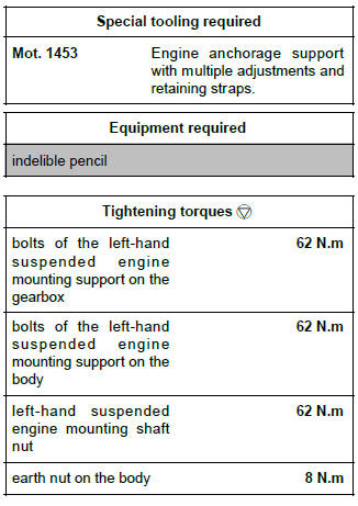
- Torque tighten the bolts of the left-hand suspended engine mounting support on the gearbox (62 N.m).
- Attach the clutch pipe.
- Refit the left-hand suspended engine mounting support on the body.
- Torque tighten the bolts of the left-hand suspended engine mounting support on the body (62 N.m).
- Refit the left-hand suspended engine mounting shaft nut.
- Torque tighten the left-hand suspended engine mounting shaft nut (62 N.m).
II - FINAL OPERATION
- Remove the tool (Mot. 1453).
- Fit the wiring channel on the left-hand suspended engine mounting.
- Refit:
- the wiring channel on the body,
- the Protection and Switching Unit,
- the petrol injection computer,
- the earth on the body.
- Torque tighten the earth nut on the body (8 N.m).
- Connect the connectors of the petrol injection computer.
- Refit:
- the air filter unit (see 12A, Fuel mixture, Air filter unit: Removal - Refitting, 12A-17),
- the battery tray (see Battery tray: Removal - Refitting) (80A, Battery),
- the battery (see Battery: Removal - Refitting) (80A, Battery),
- the air filter unit air inlet pipe,
- the front bumper (see Front bumper: Removal - Refitting) (55A, Exterior protection),
- the front wheel arch liners (see Front wheel arch liner: Removal - Refitting) (55A, Exterior protection),
- the front wheels (see Wheel: Removal - Refitting) (35A, Wheels and tyres).
- the scoop under the scuttle panel grille (see Scoop under the scuttle panel grille: Removal - Refitting) (56A, Exterior equipment),
- the scuttle panel grille (see Scuttle panel grille: Removal - Refitting) (56A, Exterior equipment),
- the windscreen wiper arms (see Windscreen wiper arm: Removal - Refitting) (85A, Wiping - Washing),
- the engine undertray.

