Renault Clio: Turbocharger oil pipe: Removal - Refitting
D4F, and 784 or 786
REMOVAL
I - REMOVAL PREPARATION OPERATION
- Position the vehicle on a two-post lift (see Vehicle: Towing and lifting) (MR 392, 02A, Lifting equipment).
- Disconnect the battery (see Battery: Removal - Refitting) (MR 392, 80A, Battery).
- Remove:
- the engine cover,
- the engine undertray,
- the front-right hand wheel driveshaft (see Front right-hand driveshaft: Removal - Refitting) (MR 392, 29A, driveshafts),
- the catalytic pre-converter (see 19B, Exhaust, Catalytic pre-converter: Removal - Refitting, 19B-23).
II - OPERATION FOR REMOVAL OF PART CONCERNED
- Remove:
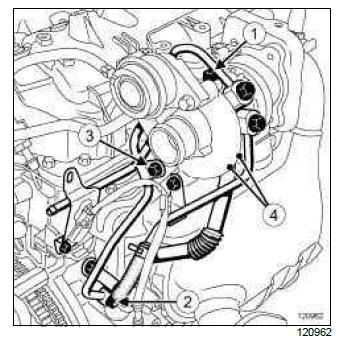
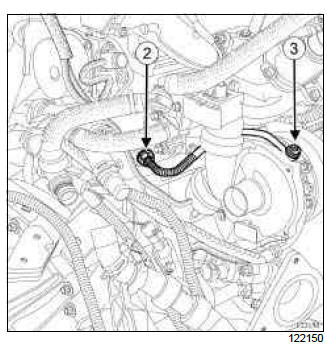
- the bolt (1) from the turbocharger oil supply pipe on the turbocharger,
- the bolt (2) on the turbocharger oil supply pipe on the cylinder block,
- the bracket bolt (3) from the turbocharger oil supply pipe,
- the turbocharger oil supply pipe,
- the bolts (4) from the turbocharger oil return pipe,
- the turbocharger oil return pipe.
- Fit a blanking plug to the opening on the cylinder block after removal of the turbocharger oil return pipe.
REFITTING
I - REFITTING PREPARATIONS OPERATION
- Always replace the turbocharger oil pipes.
- Remove the protective plug from the opening on the cylinder block.
II - REFITTING OPERATION FOR PART CONCERNED
- Refit:
- the new turbocharger oil return pipe fitted with new seals,
- the turbocharger oil return pipe bolts.
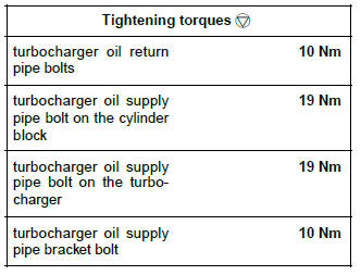
- Torque tighten the turbocharger oil return pipe bolts (10 Nm).
- Refit:
- the new turbocharger oil supply pipe fitted with its new seals,
- the turbocharger oil supply pipe bolt on the cylinder block,
- the turbocharger oil supply pipe bolt on the turbocharger,
- the turbocharger oil supply pipe bracket bolt.
- Torque tighten:
- the turbocharger oil supply pipe bolt on the cylinder block (19 Nm),
- the turbocharger oil supply pipe bolt on the turbocharger (19 Nm),
- the turbocharger oil supply pipe bracket bolt (10 Nm).
III - FINAL OPERATION.
- Refit:
- the catalytic pre-converter (see 19B, Exhaust, Catalytic pre-converter: Removal - Refitting, 19B-23),
- the front right-hand wheel driveshaft (see Front right-hand driveshaft: Removal - Refitting) (MR 392, 29A, driveshafts).
- Connect the battery (see Battery: Removal - Refitting) (MR 392, 80A, Battery).
- Check that there are no leaks:
- start the engine,
- check that the oil pressure warning light has gone out,
- leave the engine to idle,
- accelerate several times at no load,
- check that there are no oil leaks.
- Refit:
- the engine undertray,
- the engine cover.
K9K
IMPORTANT
Wear protective gloves during the operation.
WARNING
Prepare for the flow of fluid, and protect the surrounding components.
Note: This procedure deals with removing and refitting the turbocharger oil return pipe and the turbocharger oil supply pipe.
REMOVING THE TURBOCHARGER OIL SUPPLY PIPE
I - REMOVAL PREPARATION OPERATION
- Position the vehicle on a two-post lift (see Vehicle: Towing and lifting) (02A, Lifting equipment).
- Remove:
- the engine cover,
- the battery (see Battery: Removal - Refitting) (80A, Battery),
- the battery tray (see Battery tray: Removal - Refitting) (80A, Battery),
- the scuttle panel grille (see Scuttle panel grille: Removal - Refitting).
K9K, and 764 or 772
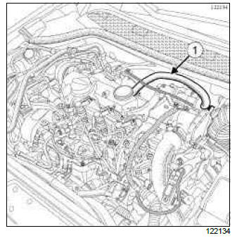
- Disconnect the oil vapour rebreathing pipe (1) on the rocker cover side.
- Undo the clips on the air outlet pipe of the air filter unit.
- Disconnect the air outlet pipe from the air filter unit.
- Remove the air outlet pipe from the air filter box.
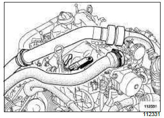
- Remove the air pipe between the turbocharger outlet and the air pipe at the intercooler inlet.
- Remove the mounting nut from the intercooler air inlet pipe on the alternator using a ratchet spanner equipped with an extension piece and a universal joint.
- Move aside the intercooler air inlet pipe.
II - OPERATION FOR REMOVAL OF PART CONCERNED
- Move the cooling hoses away from the cylinder head water chamber.
- Undo the turbocharger oil supply pipe nut (2) from the cylinder head using the (Mot. 1746).
- Remove:
- the turbocharger oil supply pipe hollow bolt (3),
- the turbocharger oil supply pipe.
REFITTING THE TURBOCHARGER OIL SUPPLY PIPE
REFITTING PREPARATION OPERATION
- parts always to be replaced: turbocharger oil supply pipe
- parts always to be replaced: Turbocharger oil supply pipe bolt
I - REFITTING OPERATION FOR PART CONCERNED
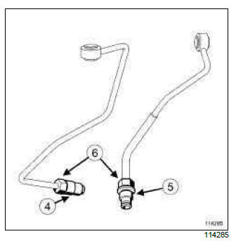
Note:
These two turbocharger oil supply pipes may be used on the same engine. The tightening torque of the end pieces (6) on the cylinder head is different, depending on the following:
- if the end piece is shouldered (5), in this case there will be no need to place the high-resistance bolt locking product on the end piece thread,
- if the end piece is not shouldered (4 ), it is essential to apply high-strength threadlock to the end piece threading.
- Refit a new turbocharger oil supply pipe.
- Fit without tightening:
- the turbocharger oil supply pipe nut on the cylinder head,
- the turbocharger oil supply pipe hollow bolt.
- Torque tighten:
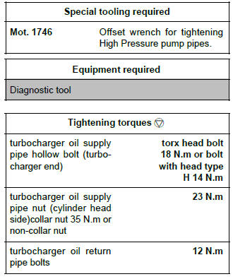
- the turbocharger oil supply pipe hollow bolt (turbocharger end) (torx head bolt 18 N.m or bolt with head type H 14 N.m),
- the turbocharger oil supply pipe nut (cylinder head side) collar nut 35 N.m or non-collar nut (23 N.m) using tool (Mot. 1746).
- Clip the cooling hoses onto the cylinder head water chamber.
II - FINAL OPERATION
- Fit:
- the turbocharger air outlet pipe,
- the retaining pins of the turbocharger air outlet pipe.
- Snap on the turbocharger air outlet pipe.
- Tighten the turbocharger air outlet pipe bolt on the rocker cover.
- Tighten the mounting nut of the intercooler air inlet pipe on the alternator using a ratchet spanner equipped with an extension piece and a universal joint.
K9K, and 764 or 772
- Connect the oil vapour rebreathing pipe on the rocker cover side.
- Refit:
- the scuttle panel grille (see Scuttle panel grille: Removal - Refitting),
- the battery tray (see Battery tray: Removal - Refitting) (80A, Battery),
- the battery (see Battery: Removal - Refitting) (80A, Battery),
- the engine cover.
Check
- Disconnect the crankshaft position sensor connector.
- Connect the battery (see Battery: Removal - Refitting) (MR 392, 80A, Battery).
- Run the starter motor until the oil pressure warning light goes out (wait for a few seconds).
- Switch off the ignition.
- Make sure that there are no oil leaks.
- Connect the Diagnostic tool and clear the stored faults.
- Connect the crankshaft position sensor connector.
REMOVING THE TURBOCHARGER OIL RETURN PIPE
I - REMOVAL PREPARATION OPERATION
- Position the vehicle on a two-post lift (see Vehicle: Towing and lifting) (02A, Lifting equipment).
- Disconnect the battery (see Battery: Removal - Refitting) (80A, Battery).
- Remove:
- the engine cover,
- the scuttle panel grille (see Scuttle panel grille: Removal - Refitting) (56A, Exterior equipment),
- the engine undertray bolts,
- the engine undertray,
- the lower engine tie-bar (see 19D, Engine mounting, Lower engine tie-bar: Removal - Refitting, 19D-13).
K9K, and 750 or 752 or 760 or 762 or 764 or 766 or 768
- Remove the catalytic converter (see 19B, Exhaust, Catalytic converter: Removal - Refitting, 19B-29).
K9K, and 772
- Remove the catalytic pre-converter (see 19B, Exhaust, Catalytic pre-converter: Removal - Refitting, 19B-23).
II - OPERATION FOR REMOVAL OF PART CONCERNED
- Remove:
- the turbocharger oil return pipe bolts on the turbocharger,
- the turbocharger oil return pipe by extracting it from the cylinder block.
REFITTING THE TURBOCHARGER OIL RETURN PIPE
I - REFITTING PREPARATION OPERATION
- parts always to be replaced: turbocharger oil pipe seal
- Oil the turbocharger oil return pipe O-ring.
II - REFITTING OPERATION FOR PART CONCERNED
- Refit new seals on the turbocharger oil return pipe.
- Fit the turbocharger oil return pipe, first positioning it in the cylinder block.
- Torque tighten the turbocharger oil return pipe bolts (12 N.m).
III - FINAL OPERATION
K9K, and 750 or 752 or 760 or 762 or 764 or 766 or 768
- Refit the catalytic converter (see 19B, Exhaust, Catalytic converter: Removal - Refitting, 19B-29).
K9K, and 772
- Refit the catalytic pre-converter (see 19B, Exhaust, Catalytic pre-converter: Removal - Refitting, 19B-23).
- Refit:
- the lower engine tie-bar (see 19D, Engine mounting, Lower engine tie-bar: Removal - Refitting, 19D-13),
- the engine undertray,
- the scuttle panel grille (see Scuttle panel grille: Removal - Refitting) (56A, Exterior equipment),
- the engine cover.
- Connect the battery (see Battery: Removal - Refitting) (80A, Battery).
Check
- Disconnect the crankshaft position sensor connector.
- Connect the battery (see Battery: Removal - Refitting) (MR 392, 80A, Battery).
- Run the starter motor until the oil pressure warning light goes out (wait for a few seconds).
- Switch off the ignition.
- Make sure that there are no oil leaks.
- Connect the Diagnostic tool and clear the stored faults.
- Connect the crankshaft position sensor connector.
READ NEXT:
 Intercooler: Removal - Refitting
K9K - D4F, and 784 or 786
Note:
Vehicles equipped with the K9K*768 engine may or
may not be equipped with an intercooler.
REMOVAL
I - REMOVAL PREPARATION OPERATION
Position the vehicle on a two-pos
Fuel circuit: Operating diagram
D4F or F4R or K4J or K4M
Operating diagram of the petrol supply circuit ( " pump - sender - fuel
filter " assembly).
The fuel system does not have a return.
The fuel pressure does not vary with eng
SEE MORE:
Driving
The Renault Clio IV (2014-2019) offers a satisfying driving experience with its nimble handling and responsive performance. Its compact size and maneuverability make it well-suited for urban driving and tight parking spaces. The precise steering and suspension tuning provide a balanced and confident
Your comfort
The Renault Clio IV (2014-2019) is designed with your comfort in mind. It features a well-crafted interior with quality materials and thoughtful ergonomics. The seats offer excellent support and adjustability, providing a comfortable driving experience. The cabin is designed to minimize noise and vi
