Renault Clio: Turbocharging: Precautions for the repair
D4F or K9K

I - TURBOCHARGER: GENERAL INSTRUCTIONS
For the turbocharging pressure regulator check (see Fault finding - Tests) (Technical Note 3419A, 12B, Turbocharging).
WARNING
The turbocharger pressure regulator rod must not be adjusted.
II - TURBOCHARGER CIRCUIT DIAGRAM
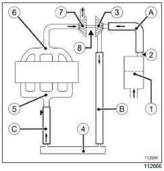
- Air filter unit
- Air flowmeter
- Compressor wheel
- Intercooler
- Inlet distributor
- Exhaust manifold
- Turbine wheel
- Bearing system (bearing + wheel shaft)
- Air filter box air outlet pipe
- Turbocharger air outlet pipe
- Intercooler air outlet pipe
III - APPLICATION CONDITIONS OF INSTRUCTIONS
The instructions below must be followed when replacing a turbocharger due to mechanical damage:
- damage to the bearing system,
- broken shaft or turbine wheel,
- compressor wheel rubbing against the turbocharger casing,
- broken or damaged compressor wheel,
- extensive clogging of the turbine wheel casing (hard deposits).
FOR THE AIR CIRCUIT:
- Consequences:
- swarf or metal objects in the turbocharger inlet and outlet pipes,
- oil in the air circuit (collected in the intercooler).
- Risks (after replacing the turbocharger):
- metal objects sucked in by the compressor wheel (destruction of the turbocharger).
FOR THE LUBRICATION CIRCUIT:
- Consequences:
- swarf found in the engine oil circuit,
- circulation of swarf within the circuit.
- Risks (after replacing the turbocharger):
- premature wear on the bearing system (destruction of turbocharger).
WARNING
Metal objects may enter the oil and air circuits as a result of a broken turbocharger.
Failure to follow the INSTRUCTIONS listed will lead to the turbocharger breaking again.
INSTRUCTIONS:
- Drain the engine oil (see 10A, Engine and cylinder block assembly, Engine oil: Draining - Refilling, 10A-12)
- Replace the oil filter (see 10A, Engine and cylinder block assembly, Oil filter: Removal - Refitting, 10A-19).
- Replace the seals and fittings,
- Carry out the following only if the compressor wheel is
broken or rubbing against the turbocharger casing:
- Drain the intercooler,
- Clean the turbocharger air pipes.
Note: When carrying out an operation on the air or lubrication circuit, it is necessary to plug the open holes to prevent any risk of foreign bodies entering the system.
IV - AIR CIRCUIT*: INSTRUCTIONS FOLLOWING MECHANICAL DAMAGE TO THE TURBOCHARGER
Note:
(*) These instructions for the air circuit are only to be followed in the case of:
- broken compressor wheel,
- compressor wheel rubbing against the turbocharger casing.
Remove the intercooler if fitted to the vehicle (see 12B, Turbocharging, Intercooler: Removal - Refitting, 12B-21).
Turn the intercooler over and allow the oil inside to drain out.
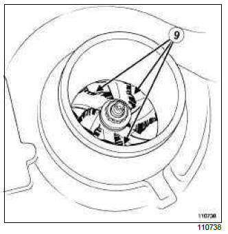
Note: If the compressor wheel (9) is damaged, metal objects are ejected inside the air pipes.
Check that there are no metal objects inside the air flowmeter (2).
Remove:
- the air pipe (between the air filter unit and the turbocharger) (A),
- the air pipe (B) (between the turbocharger and the intercooler).
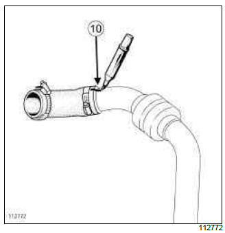
For air pipes comprising several components:
- mark (10) the fitting position of each component,
- separate all the components.
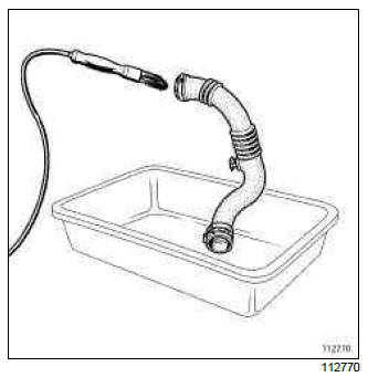
One by one, clean the pipes removed with the parts washer :
- brush as much of the inside of the pipe as possible (only use brushes with plastic bristles),
- wash plenty of cleaning product from the cleaning station through the pipe,
- allow the cleaned pipe to drain by standing it upright,
- ensure the cleaning product has drained out completely (check areas where liquid may be retained, e.g. gaiters, resonators etc.).
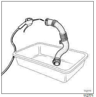
Dry the pipes one by one using a compressed air spray gun.
For pipes comprising several components:
- assemble the components, taking note of their correct fitting position (10).
Refit:
- the air pipe (between the air filter unit and the turbocharger) (A),
- the air pipe (B) (between the turbocharger and the intercooler).
Refit the intercooler, if fitted to the vehicle (see 12B, Turbocharging, Intercooler: Removal - Refitting, 12B-21).
V - LUBRICATION CIRCUIT**: INSTRUCTIONS FOLLOWING MECHANICAL DAMAGE TO THE TURBOCHARGER
Note: (**) These instructions relating to the lubrication circuit must always be followed in all cases of mechanical damage as listed above.
Drain the engine oil (see 10A, Engine and cylinder block assembly, Engine oil: Draining - Refilling, 10A-12).
Replace the oil filter (see 10A, Engine and cylinder block assembly, Oil filter: Removal - Refitting, 10A-19).
Only fill the engine with a suitable oil type (see Engine oil: Specifications) (Technical Note 6013A, 04A, Lubricants).
VI - GENERAL INSTRUCTIONS TO BE FOLLOWED WHEN REMOVING A TURBOCHARGER
Always replace:
- the oil supply pipe:
- if the pipe is blocked, even partially (due to scale, carbonised oil etc.),
- if the pipe is fitted with self-retaining seals.
- the oil return pipe:
- if the pipe is blocked, even partially (due to scale, carbonised oil etc.),
- if the pipe is fitted with self-retaining seals.
- all seals that have been removed,
- all fittings that have been removed.
WARNING
Failure to observe the following procedure may lead to destruction of the turbocharger.
When starting the engine:
- do not accelerate,
- allow the engine to run for 1 minute, the time taken for the oil circuit pressure to increase (until the oil pressure warning light on the instrument panel goes out),
- accelerate several times at no load,
- check the air circuit and the oil circuit for leaks.

