Renault Clio: D4F
REMOVAL
I - REMOVAL PREPARATION OPERATION
- Position the vehicle on a two-post lift (see Vehicle: Towing and lifting) (MR 392, 02A, Lifting equipment).
- Disconnect the battery (see Battery: Removal - Refitting)
(MR 392, 80A, Battery).
- Remove:
- the engine cover,
- the engine undertray,
- the front right-hand wheel (see Wheel: Removal - Refitting) (MR 392, 35A, Wheels and tyres),
- the front right-hand wheel arch liner (see Front wheel arch liner: Removal - Refitting) (MR 393, 55A, Exterior protection),
- the accessories belt (see 11A, Top and front of engine, Accessories belt: Removal - Refitting, 11A-5),
- the front bumper (see Front bumper: Removal - Refitting) (MR 393, 55A, Exterior protection).
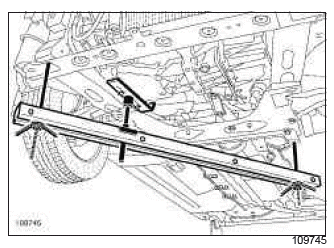
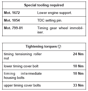
- Fit the engine support tool (Mot. 1672) under the lower cover.
- Remove:
- the crankshaft accessories pulley (see 11A, Top and front of engine, Crankshaft accessories pulley: Removal - Refitting, 11A-31),
- the right-hand suspended engine mounting (see 19D, Engine mounting, Right-hand suspended engine mounting: Removal - Refitting, 19D-22).
II - OPERATION FOR REMOVAL OF PART CONCERNED
- Remove:
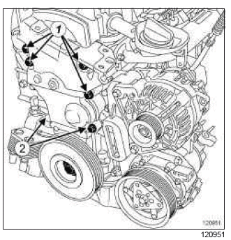
- the bolts (1) from the upper timing cover,
- the upper timing cover,
- the bolts (2) from the timing intermediate housing,
- the middle timing cover.
- Remove:
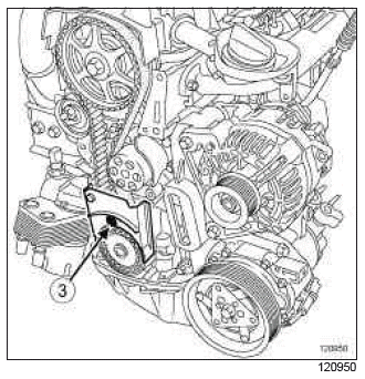
- the lower timing cover bolt (3),
- the lower timing cover.
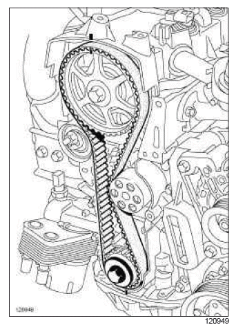
- Refit the crankshaft accessories pulley bolt and its retaining washer.
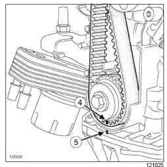
- Turn the crankshaft clockwise (timing end) to position the crankshaft sprocket marking (4) half a tooth in front of the alignment of the fixed marking (5) on the oil pump casing.
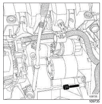
- Insert (Mot. 1054).
- Turn the crankshaft clockwise until it is stopped.
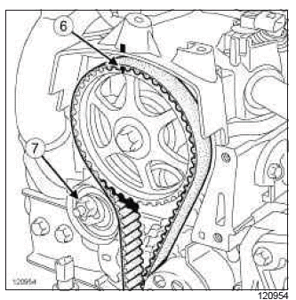
- Check that mark (6) of the camshaft sprocket is vertical to the engine and aligned with the rocker cover mark.
- Undo the timing tension wheel nut (7).
- Loosen the timing tension wheel by turning the eccentric cam using a 6 mm Allen key.
- Remove:
- the timing belt,
- the timing tensioning roller nut,
- the timing tensioning roller.
REFITTING
I - REFITTING PREPARATIONS OPERATION
- parts always to be replaced: Timing belt.
- parts always to be replaced: Timing belt tensioning roller.
- parts always to be replaced: Crankshaft accessories pulley bolts
II - REFITTING OPERATION FOR PART CONCERNED
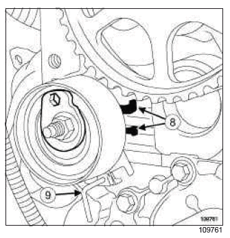
- Refit the new tensioning roller.
- Position both indexes (8) between the cylinder head groove.
- Do not remove the pin (9) before refitting the timing belt.
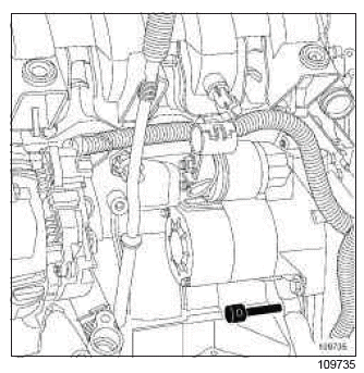
- Check that the crankshaft is at its setting point using the (Mot. 1054).
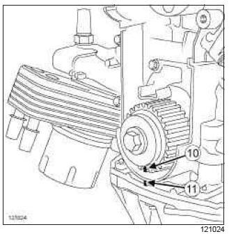
- The mark on the crankshaft sprocket (10) must be aligned with the fixed marking (11) on the oil pump casing.
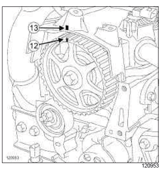
- Align the mark on the camshaft sprocket (12) with the fixed marking (13) on the rocker cover using the (Mot. 799-01).
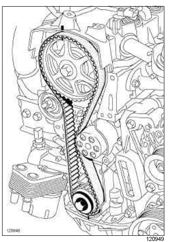
- Torque tighten the crankshaft accessories pulley bolt (15 Nm).
- Fit the timing belt, aligning the marks on the belt with those on the crankshaft sprocket and camshaft sprocket.
- Remove the (Mot. 1054).
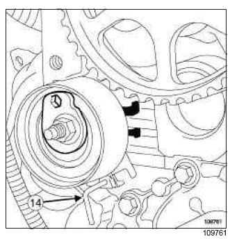
- Remove the pin (14) from the timing tensioning roller.
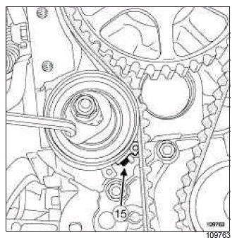
- Turn the tensioning roller eccentric in an anti-clockwise direction using a 6 mm Allen key.
- Move the adjustable index (15) on the tensioning roller into the position indicated above.
- Torque tighten the timing tensioning roller nut (24 Nm).
- Rotate the crankshaft through six revolutions in a clockwise direction (timing end).
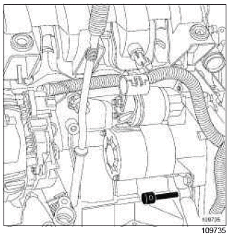
- Insert (Mot. 1054).
- Rotate the crankshaft to the setting point.
- Check that the camshaft and crankshaft sprockets markings are correctly aligned with the fixed markings.
- Remove the (Mot. 1054).
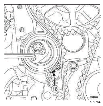
- Loosen the tensioning roller nut by up to one turn, holding the eccentric with a 6 mm Allen key.
- Turn the adjustable index (16) on the tensioning roller in a clockwise direction into the position indicated above.
- Tighten to torque the timing tensioning roller nut (24 Nm).
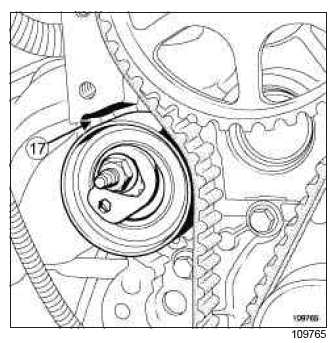
- Check that the tensioning roller does not come into contact with the cylinder head (17).
Note:
If the tensioning roller is in contact with the cylinder head:
- set the engine to Top Dead Centre,
- remove the tensioning roller and the timing belt,
- reposition the tensioning roller pin,
- repeat the timing belt refitting procedure, step by step, from the beginning.
- Remove the crankshaft accessories pulley bolt.
- Refit:
- the lower timing cover,
- the lower timing cover bolt.
- Torque tighten the lower timing cover bolt (10 Nm).
- Refit:
- the timing intermediate housing,
- the timing intermediate housing bolts.
- Torque tighten the timing intermediate housing bolts (10 Nm).
- Refit:
- the upper timing cover,
- the upper timing cover.
- Tighten to torque the upper timing cover bolts (33 Nm).
III - FINAL OPERATION.
- Refit:
- the right-hand suspended engine mounting (see 19D, Engine mounting, Right-hand suspended engine mounting: Removal - Refitting, 19D-22),
- the crankshaft accessories pulley (see 11A, Top and front of engine, Crankshaft accessories pulley: Removal - Refitting, 11A-31),
- the accessories belt (see 11A, Top and front of engine, Accessories belt: Removal - Refitting, 11A-5).
- Remove the lower engine support tool (Mot. 1672).
- Refit:
- the front bumper (see Front bumper: Removal - Refitting) (MR 393, 55A, Exterior protection),
- the front right-hand wheel arch liner (see Front wheel arch liner: Removal - Refitting) (MR 393, 55A, Exterior protection),
- the front right-hand wheel (see Wheel: Removal - Refitting) (MR 392, 35A, Wheels and tyres),
- the engine undertray,
- the engine cover.
- Connect the battery (see Battery: Removal - Refitting) (MR 392, 80A, Battery).
READ NEXT:
 K4M
K4M
REMOVAL
I - REMOVAL PREPARATION OPERATION
Position the vehicle on a two-post lift (see Vehicle:
Towing and lifting) (02A, Lifting equipment).
Remove:
the engine undertray bolts,
the engine u
 K9K, and 766 or 768
IMPORTANT
Wear protective gloves during the operation.
WARNING
Never rotate the engine anti-clockwise (timing end).
WARNING
Do not run the engine without the accessories belt
so as not to damage the
 K4J
K4J
REMOVAL
I - REMOVAL PREPARATION OPERATION
Position the vehicle on a two-post lift (see Vehicle:
Towing and lifting) (02A, Lifting equipment).
Remove:
the scuttle panel grille (see Scuttle pane
SEE MORE:
 Master cylinder: Removal - Refitting
F4R or K4J or K4M or K9K or M4R, and LEFT-HAND DRIVE
WARNING
Prepare for brake fluid outflow, to prevent damage
to the mechanical parts and bodywork around the
braking system.
REMOVAL
I - REMOVAL PREPARATION OPERATION
Position the vehicle on a two-post lift (see Vehicle:
Towing and lifting) (MR
 Practical advice
Here are some practical advice points for the Renault Clio IV (2014-2019):
Regular Maintenance: Follow the recommended maintenance schedule outlined in the owner's manual to keep your Clio IV running smoothly. This includes regular oil changes, filter replacements, and inspections of import
© 2016-2026 Copyright Renault Clio Owners Club

